Razor Crest Lighting Kit
Getting Ready
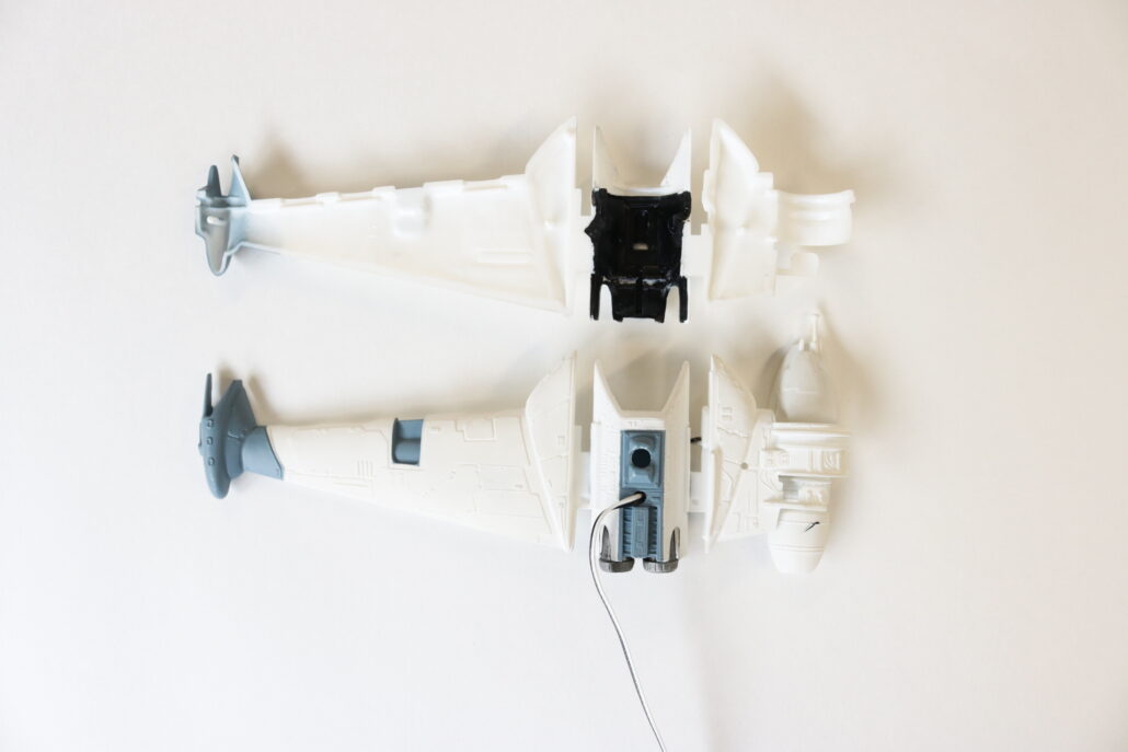
First start by getting yourself familiar with all the model kit parts & where they are positioned to assemble the model. Second read all the information regarding the model lighting kit & wiring diagram. There are only a few modifications that will need to be made to the model before the lighting system install. This lighting system is more advanced & will require electronic knowledge.
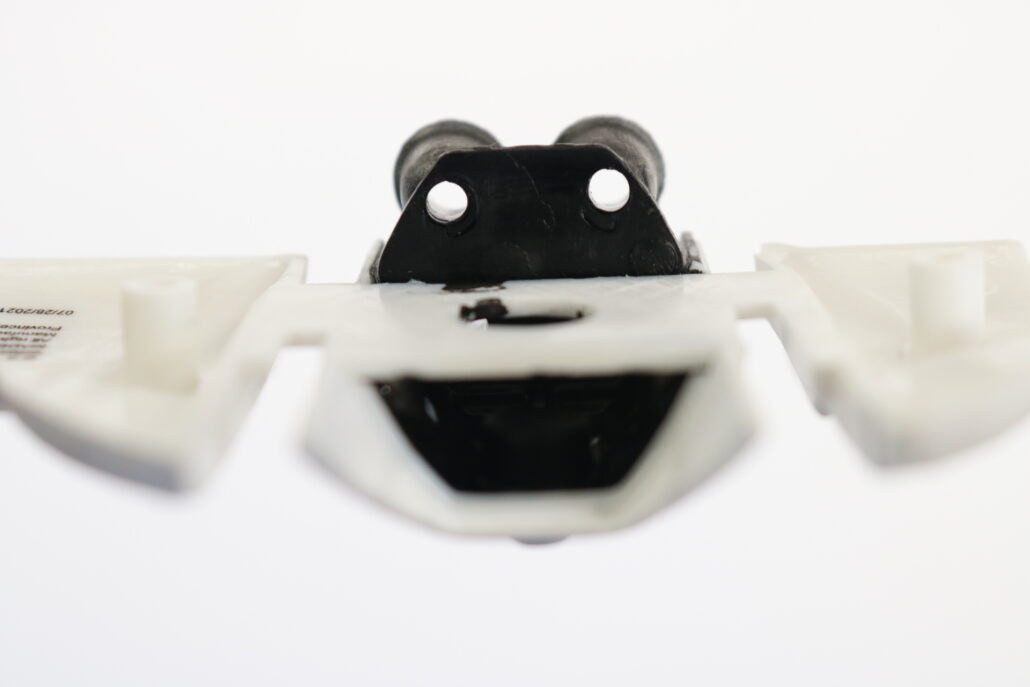
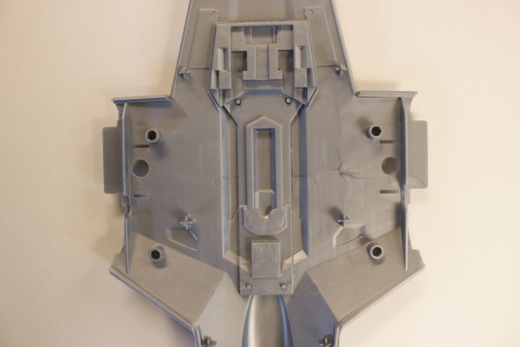
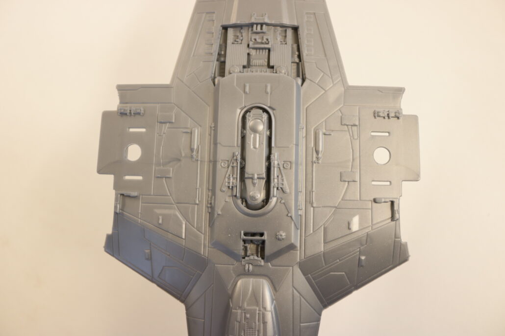
Preparing The Body
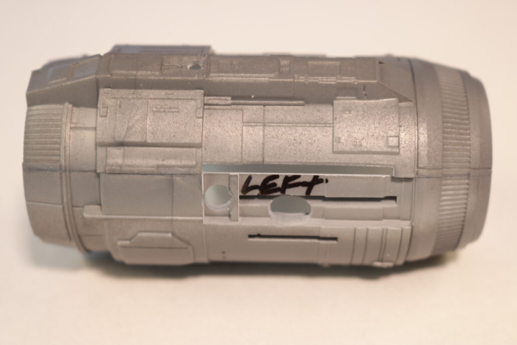
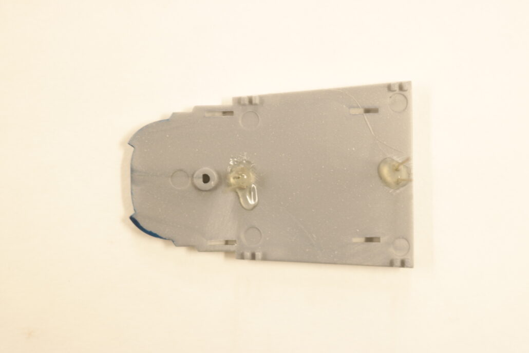
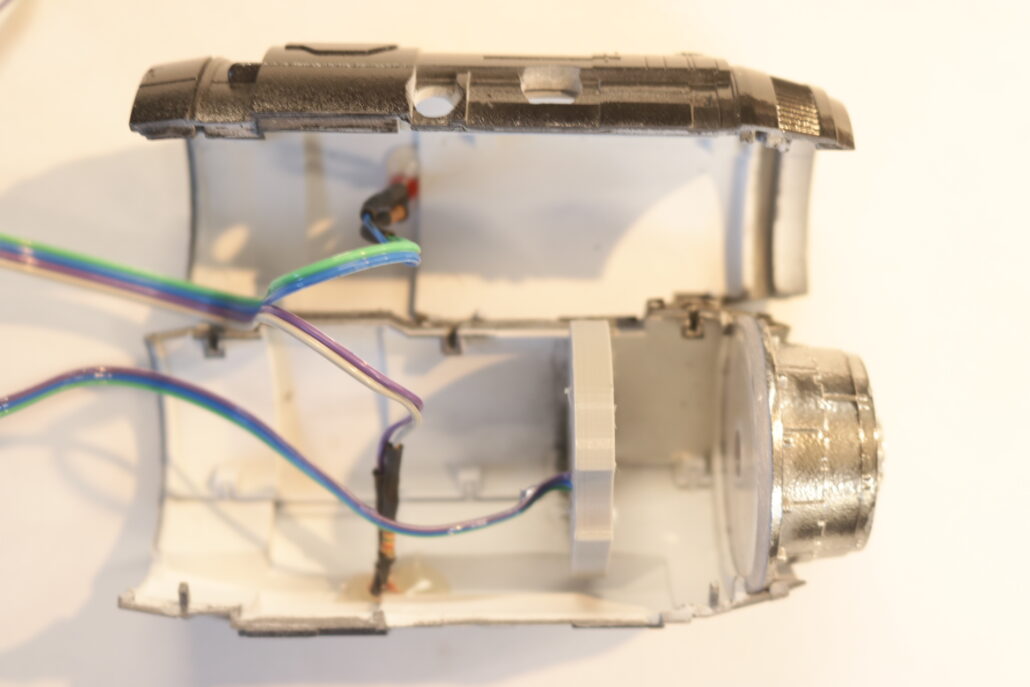
One of the first steps is drilling out the main body to transfer wiring into the main body where the controller board is stored. The more passage ways you have for wiring the better, but keep in mind that you are transferring your holes with in the areas inside the model only.
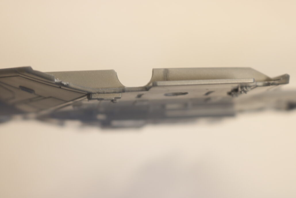
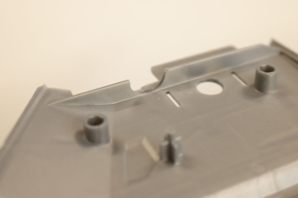
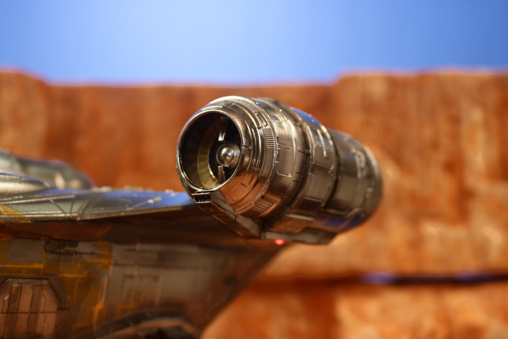
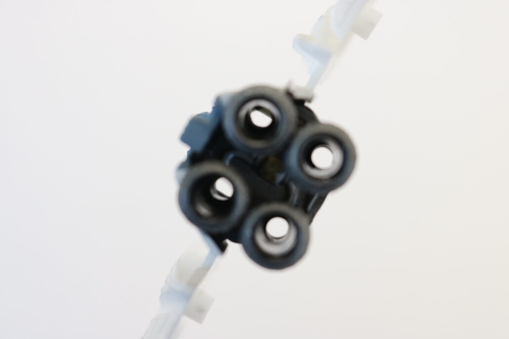
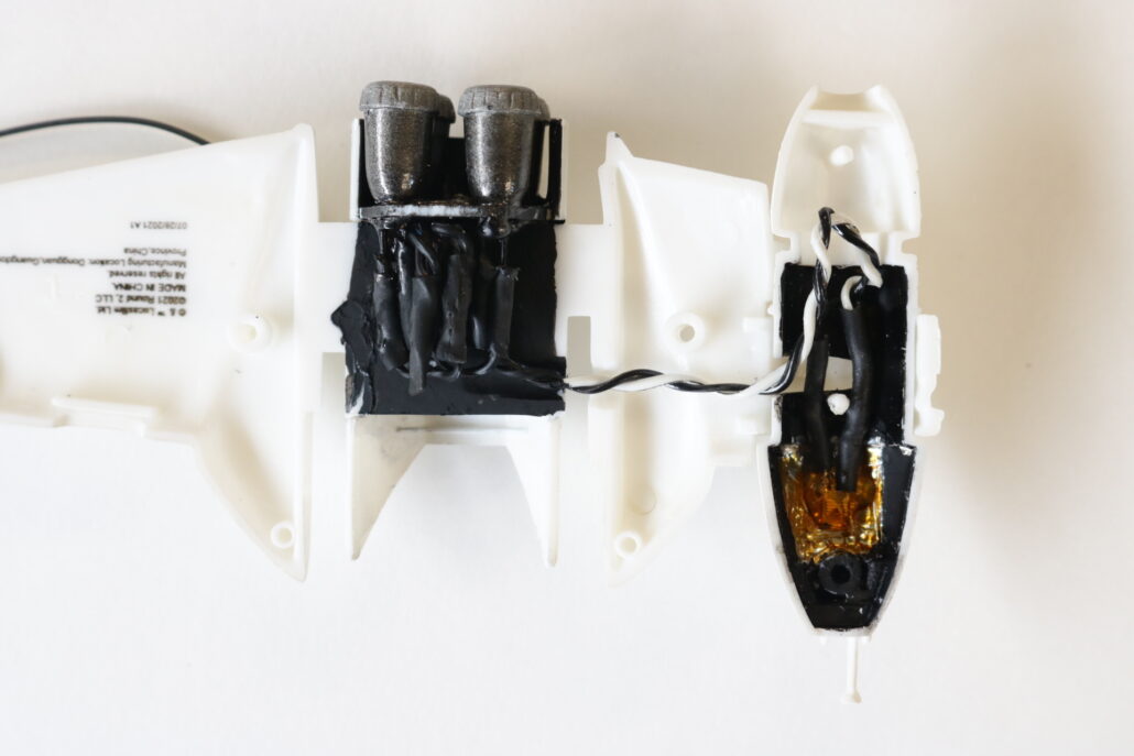
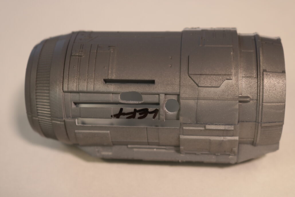
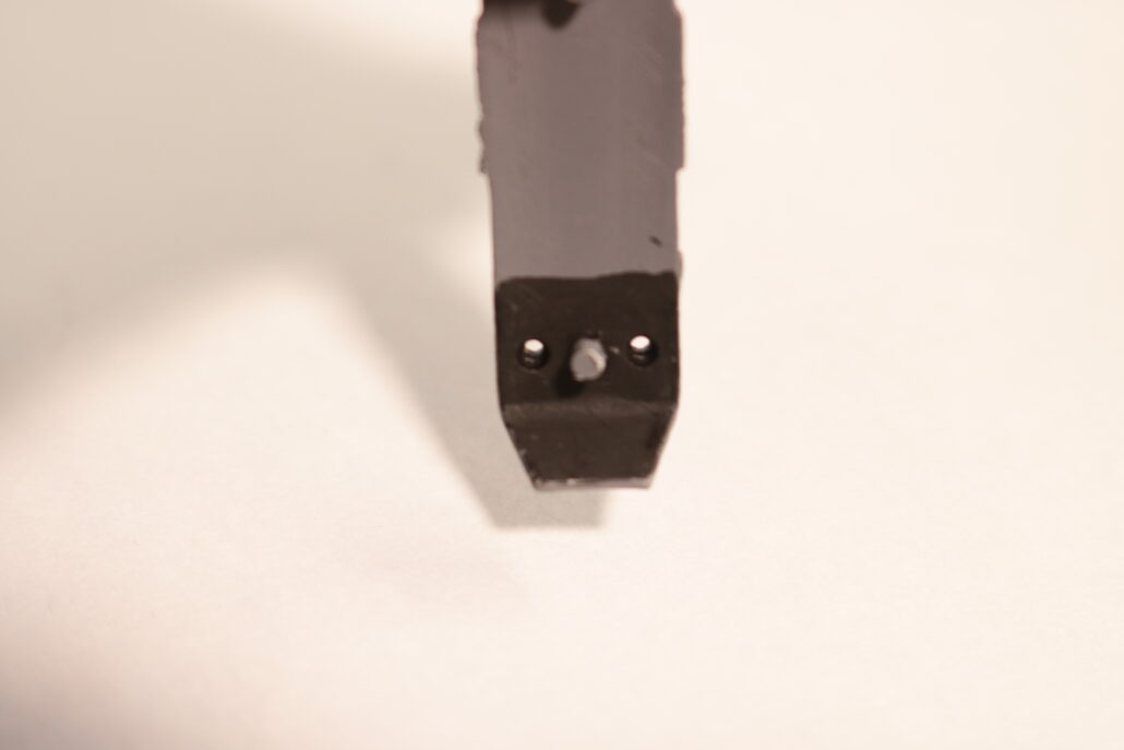
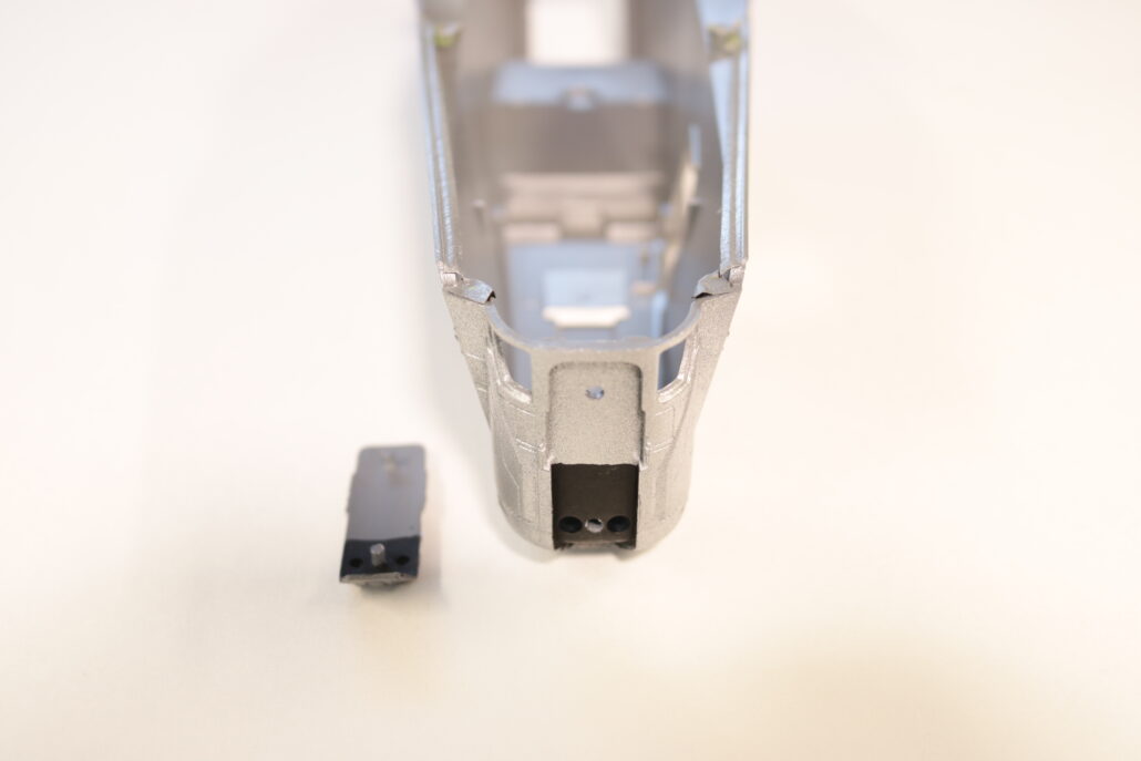
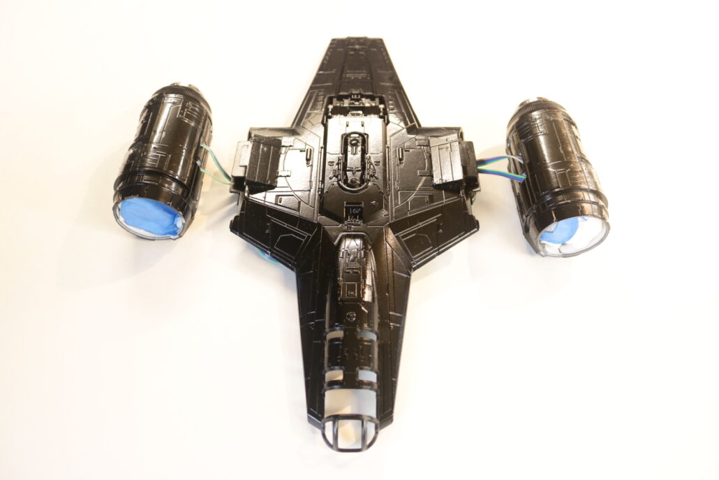
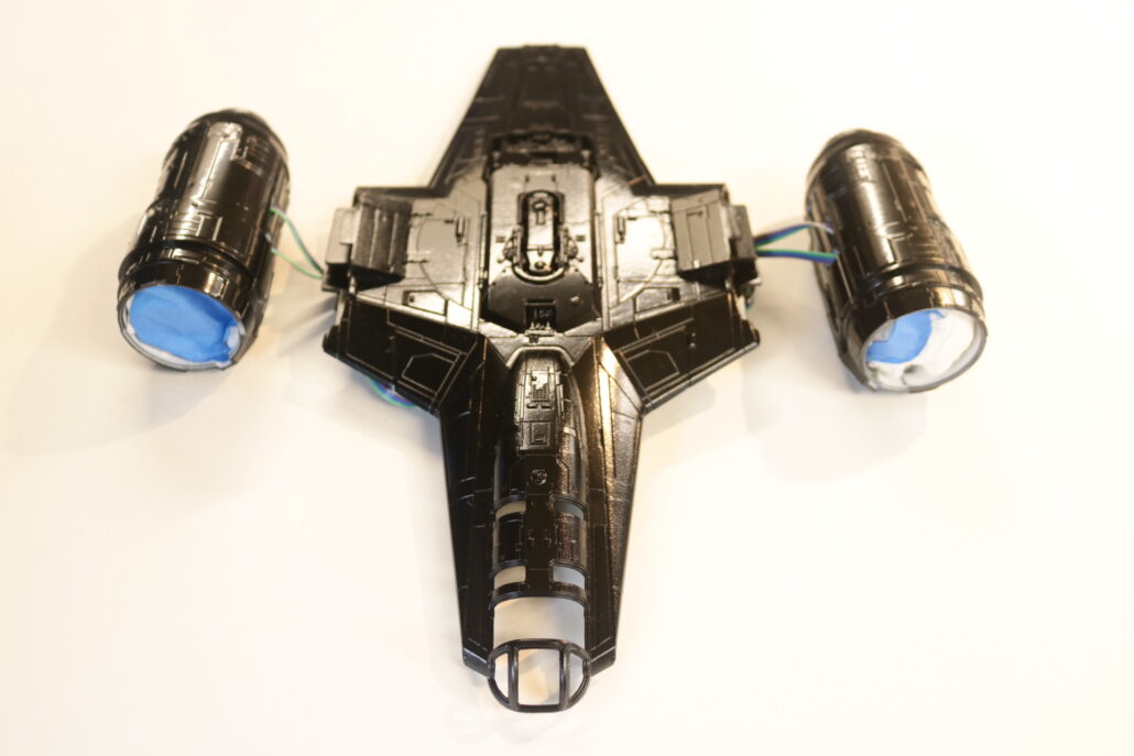
Preparing The Engines
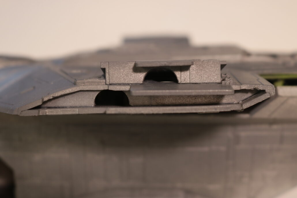
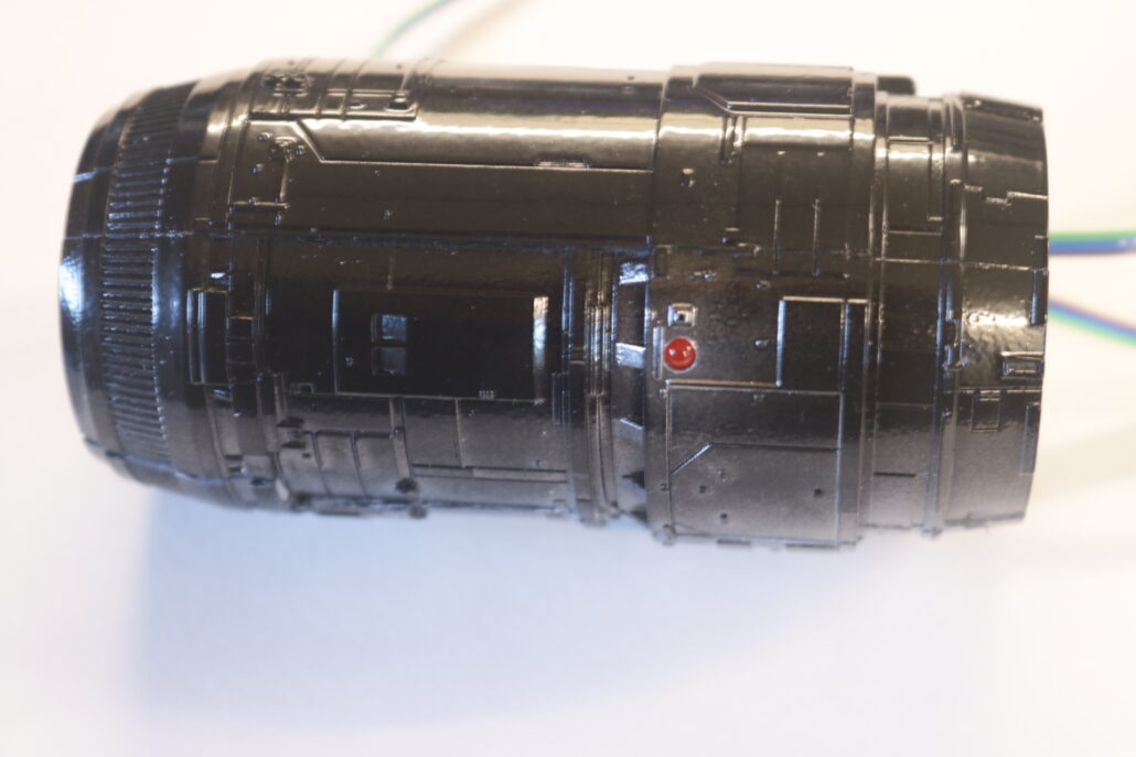
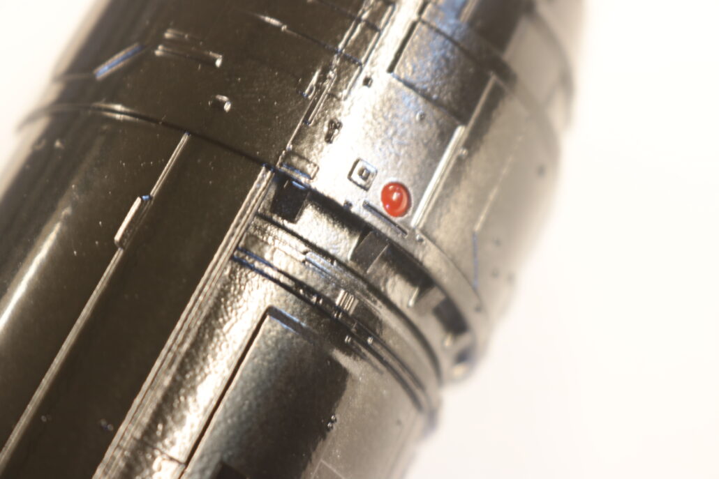
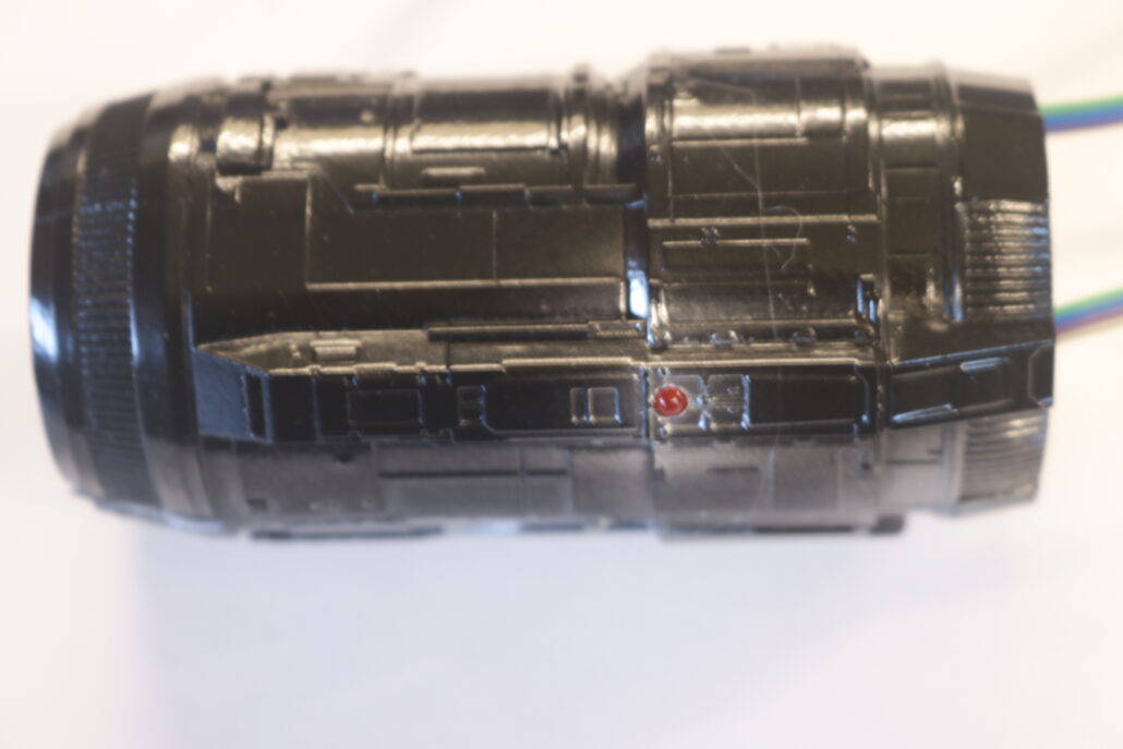
One of the second step is to cut out all the small rear engine shroud slots, I used a hobby knife & some super fine files. The next step there will need to be some porting in and around the engine nacelles. The upper engine mounting blocks will also need drilling & porting. I have added some free downloadable 3D files for internal engine display brackets (THE BRACKETS ARE NOT INCLUDED IN THE KIT) you will need to 3D print them or scratch build the brackets on your own. This also a good time to drill out for all the red diffused marker or position lights, there are two small pairs in the very front drill outs that need need to be made behind the front face part, you want to be careful not to drill all the way through with the 3mm drill bit. All the other marker or position lights are on the upper & lower areas of the forward section of the nacelle.

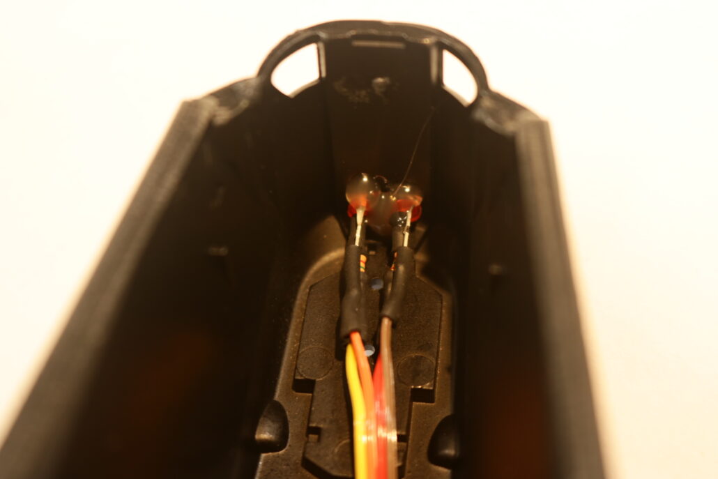
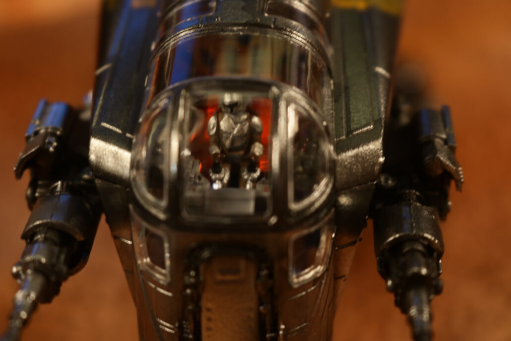
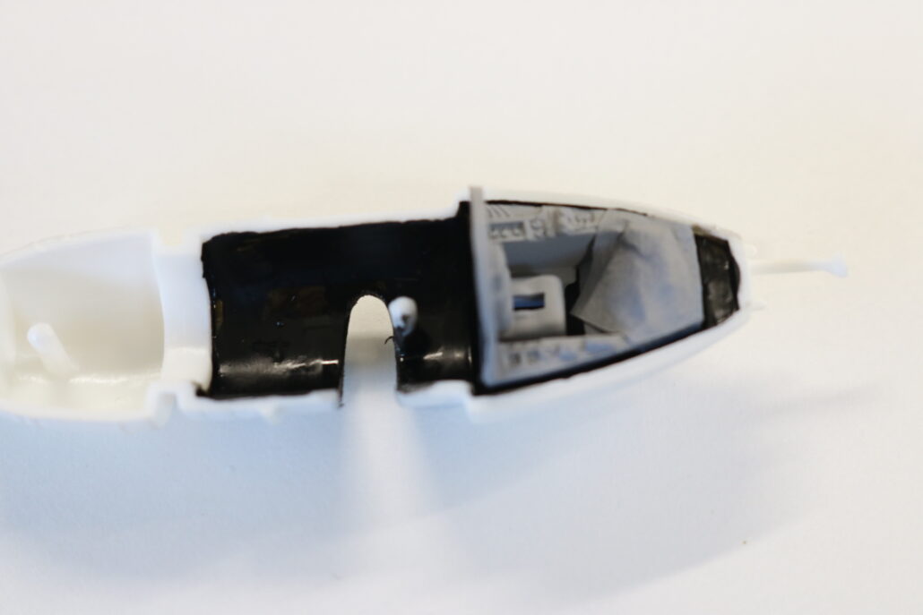
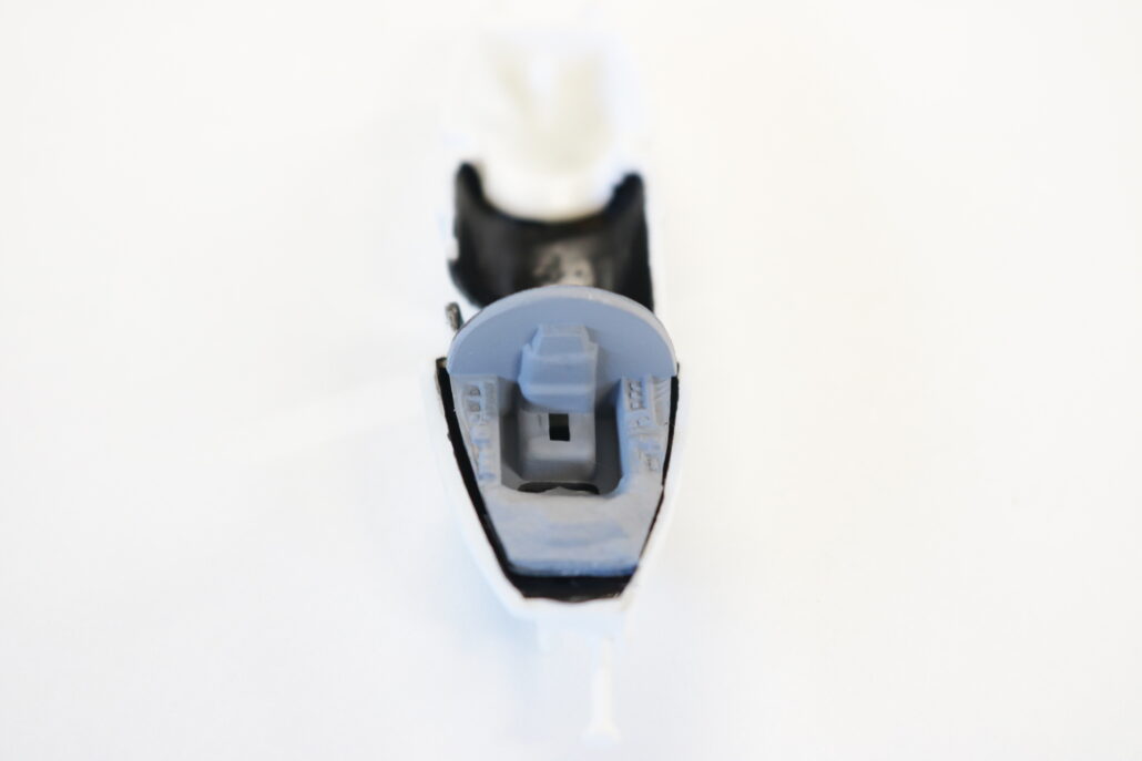
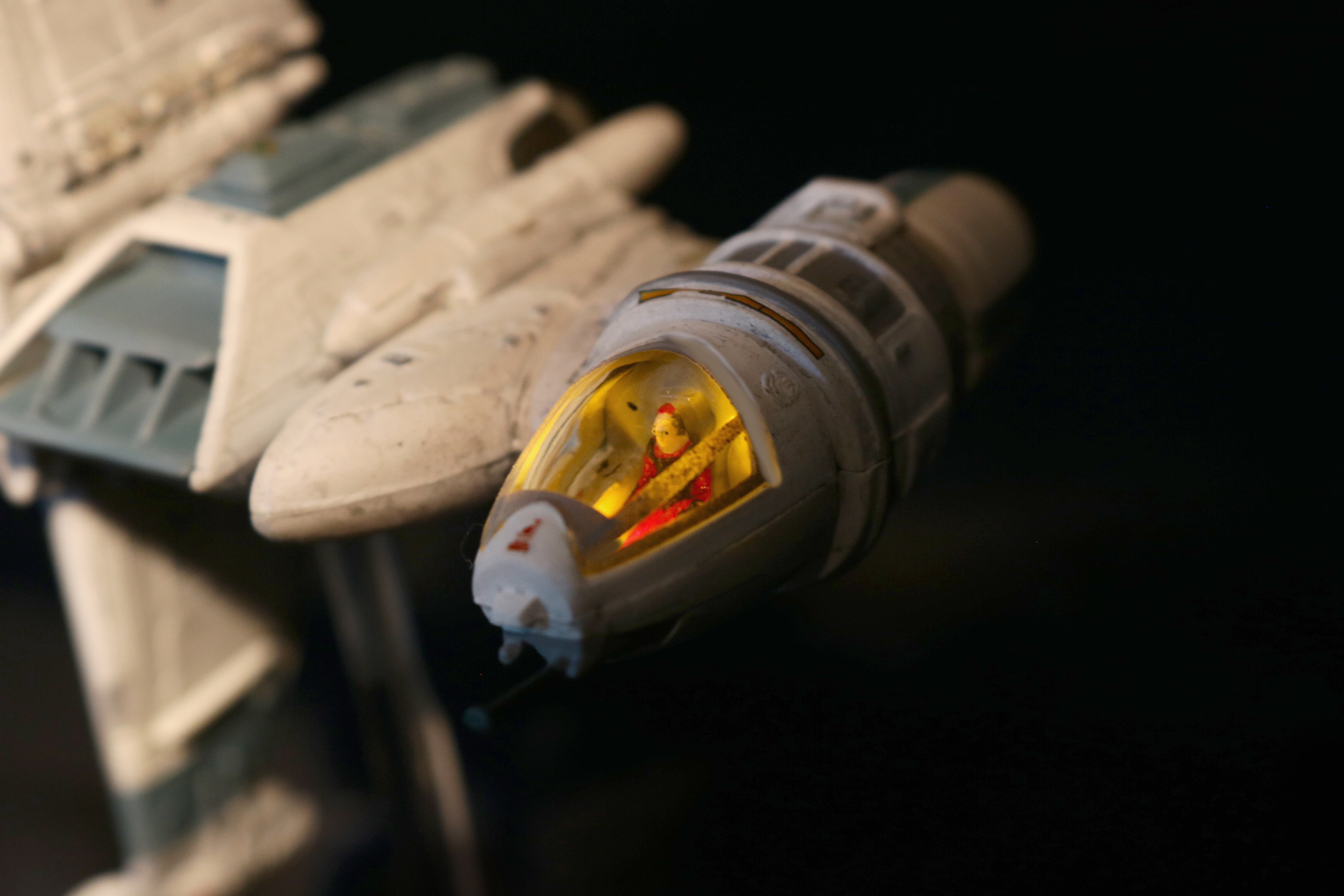
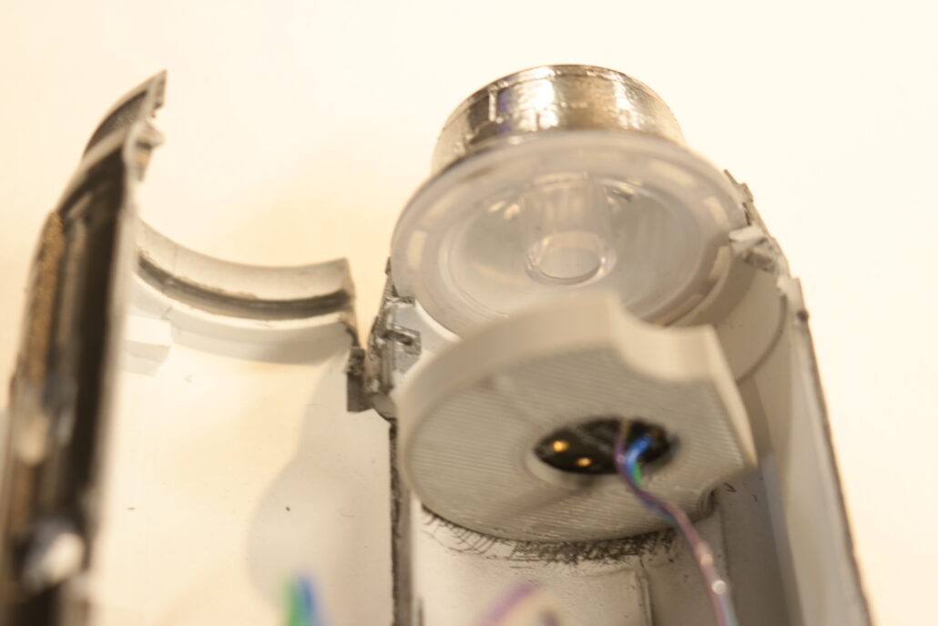
Cockpit
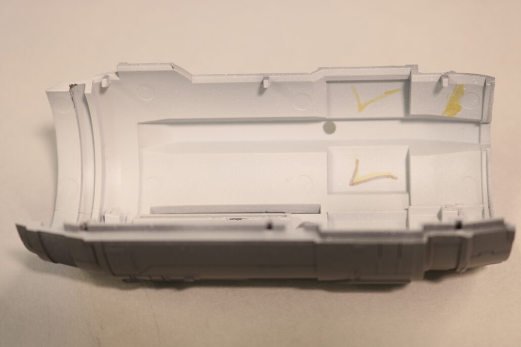
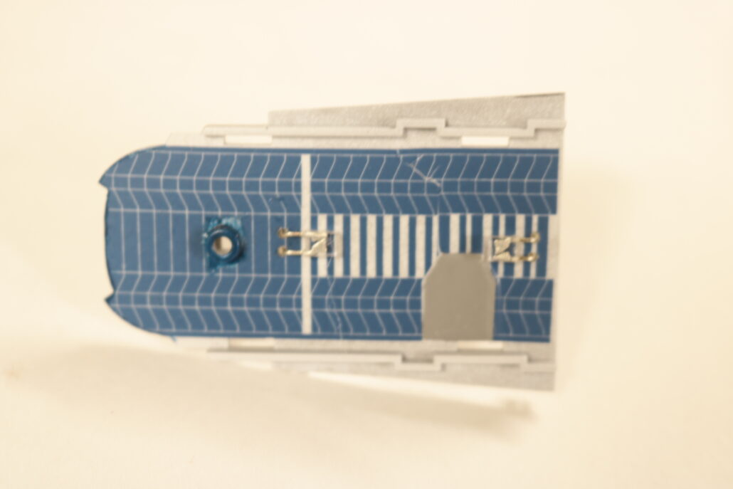
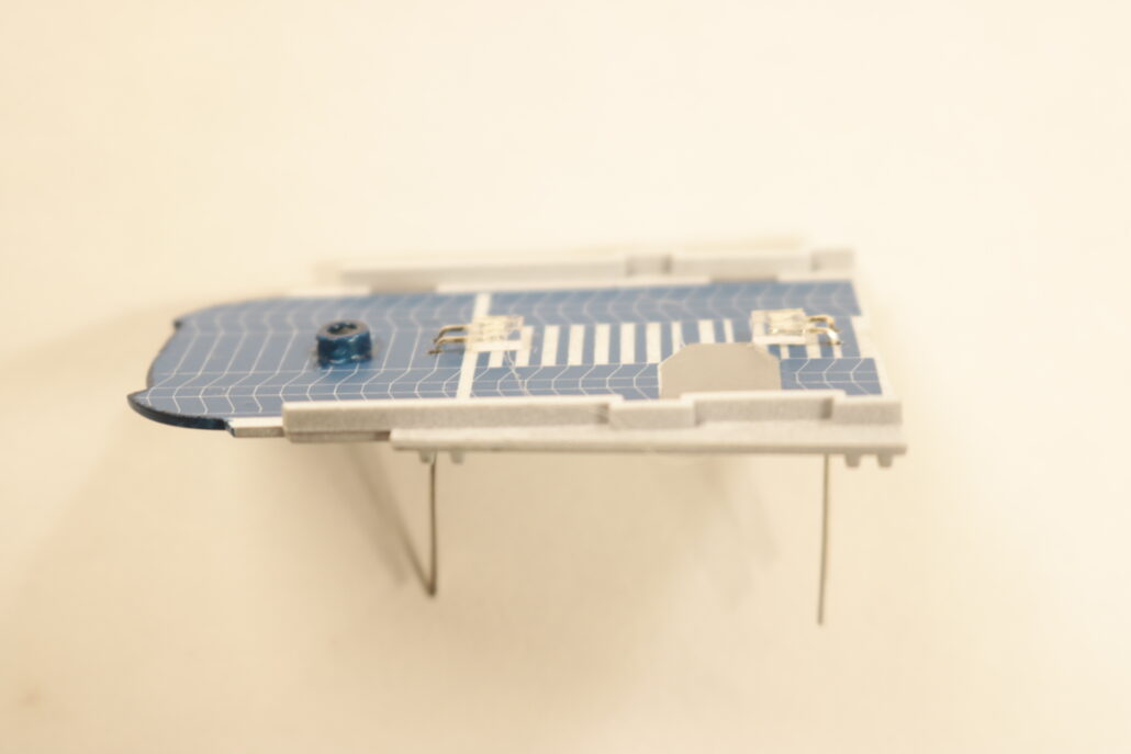
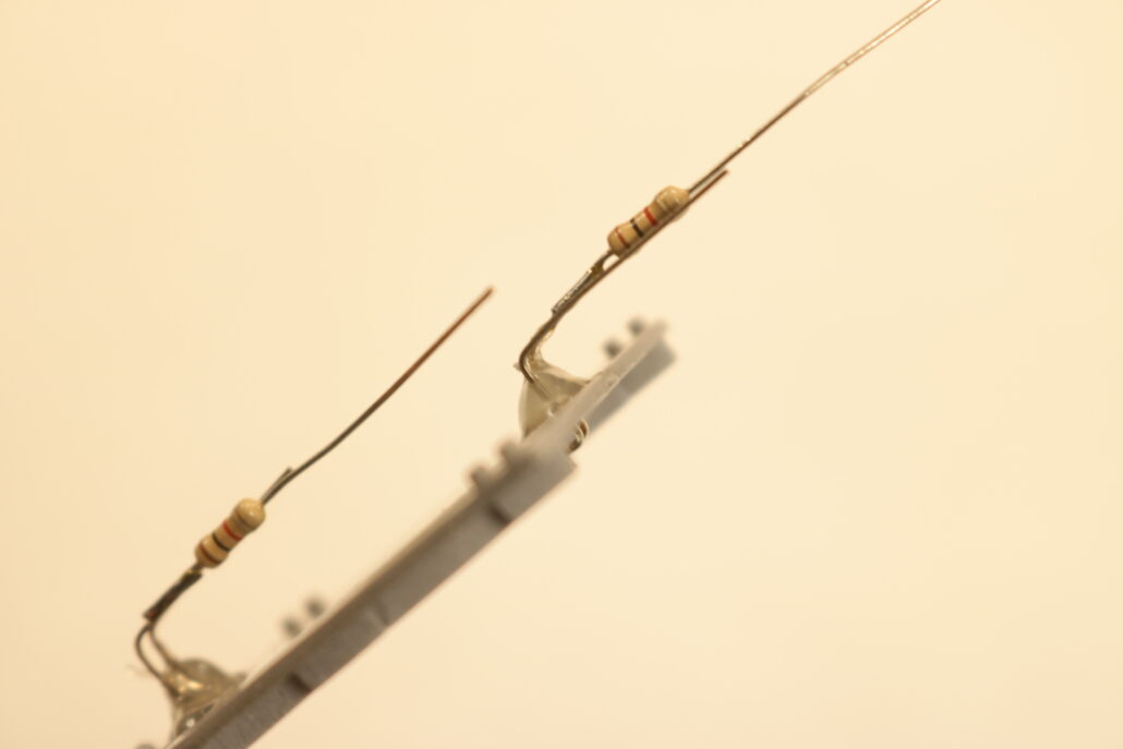
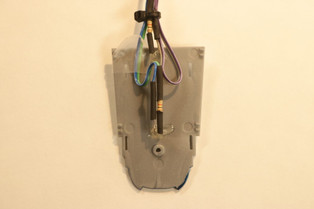
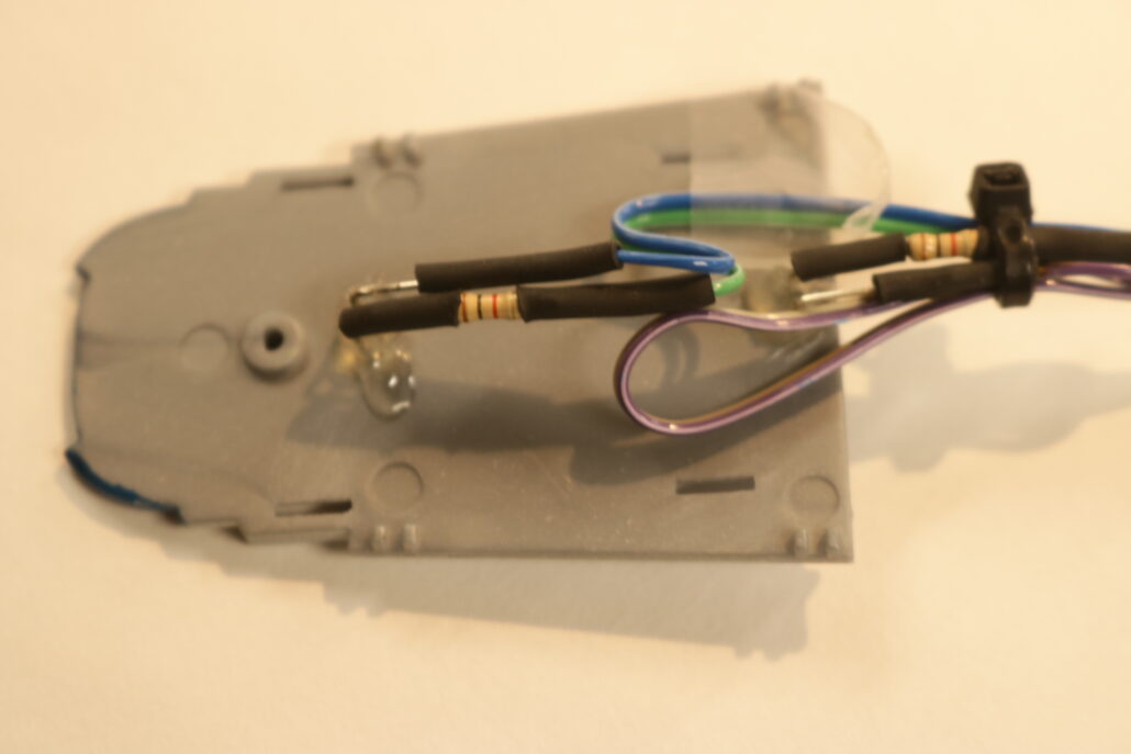
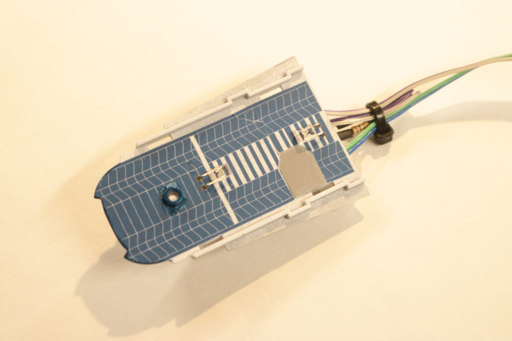
In the cockpit I took a floor lighting approach, by mounting two small square leds bent at a 90 degree angle flush mounted to the floor. There are two zones, FORWARD MAIN COCKPIT & AFT MECHANICAL ROOM. You will need to drill out with a #64 bit pinvise four small enough holes to send led leads through the floorboard. Its easiest to bend the led leads on the bottom side of the floor & solder your resistors, wire & shrink tubing. I prebuilt the floor with the leds mounted before I put the interior together and mounted it in the model.

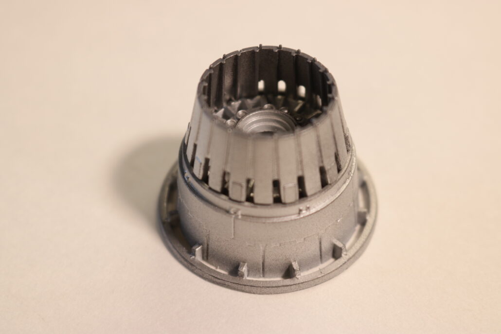
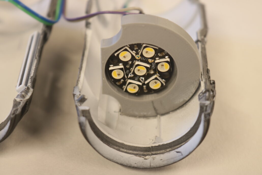
Engine Display Boards
After all the parts have been almost 100% pre painted you can start figuring out the display bracket. This is also a good time to finish off the the rest of the nacelle marker lights & wire them in place. There are two ways of making the display brackets that hold them, A I give you the free stl file & you print them or B you scratch build the display holder. The free file for the bracket is on the order page.
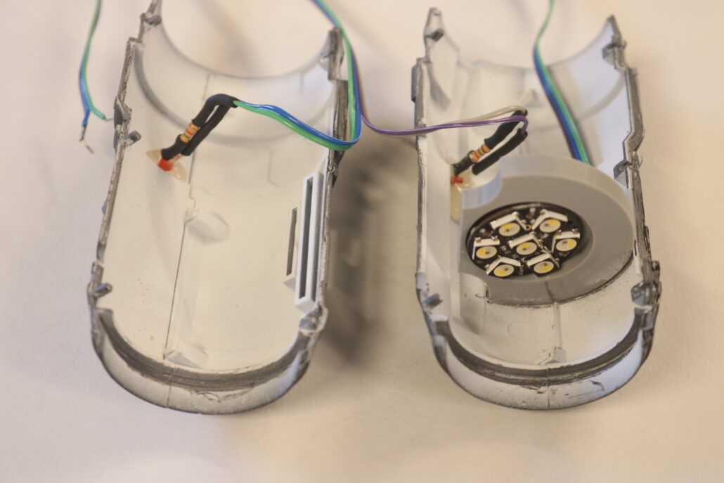
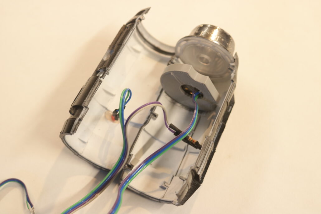
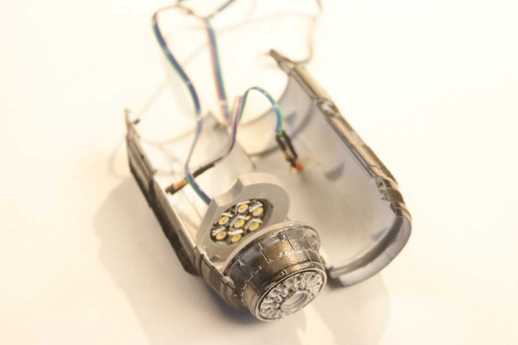
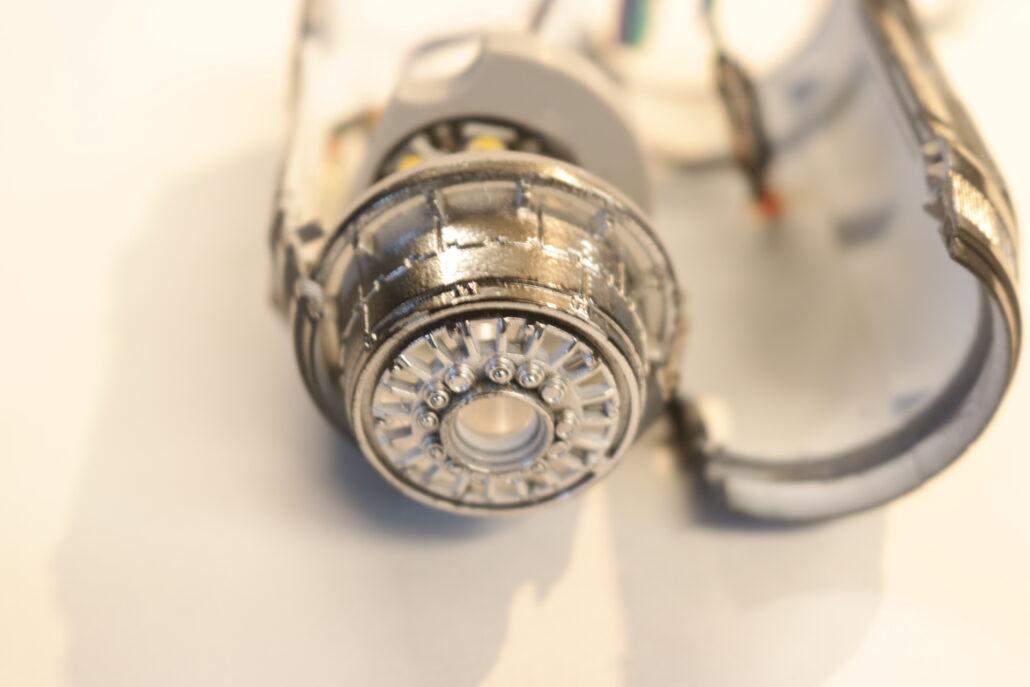


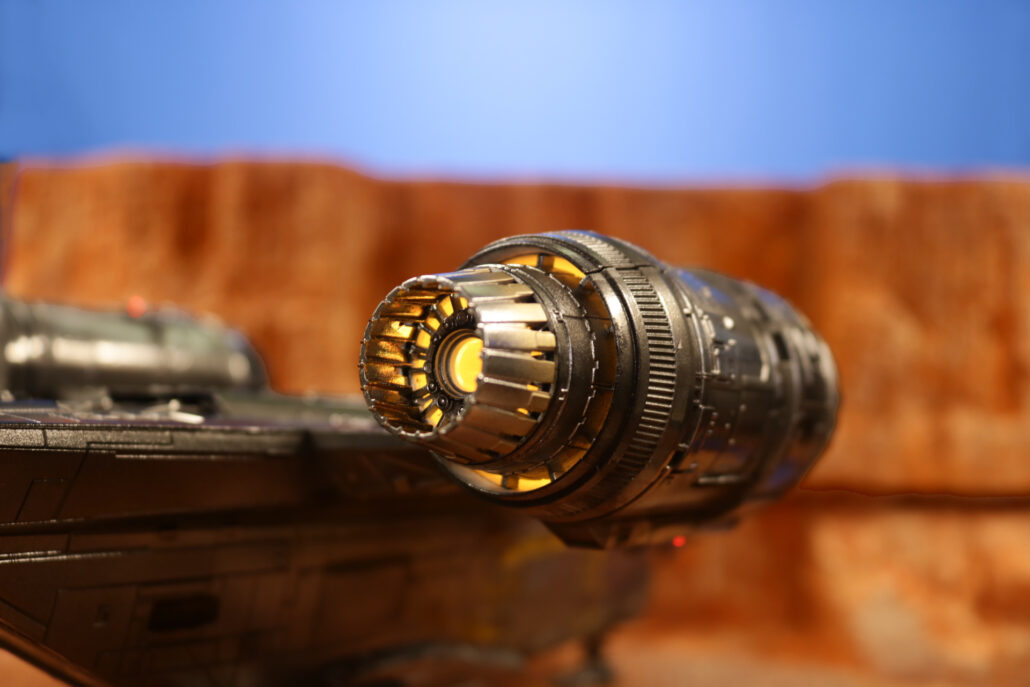
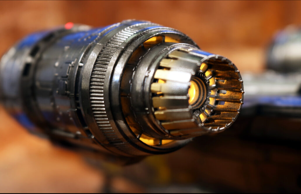
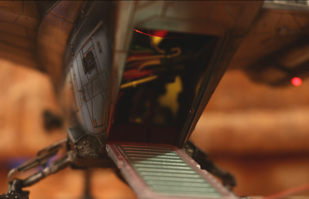
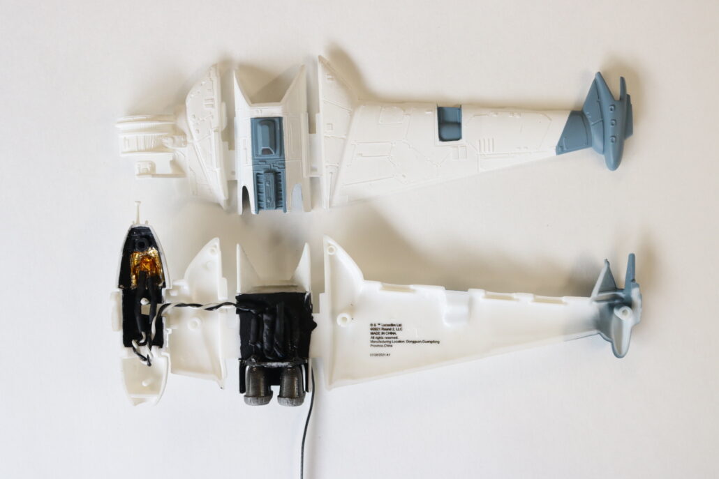
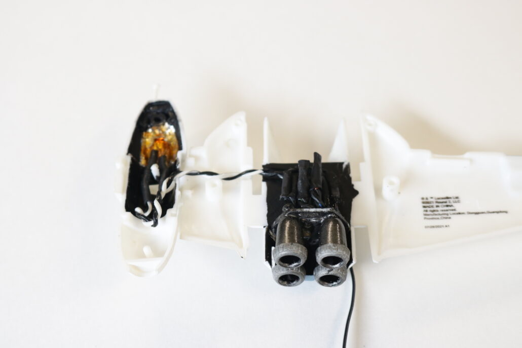
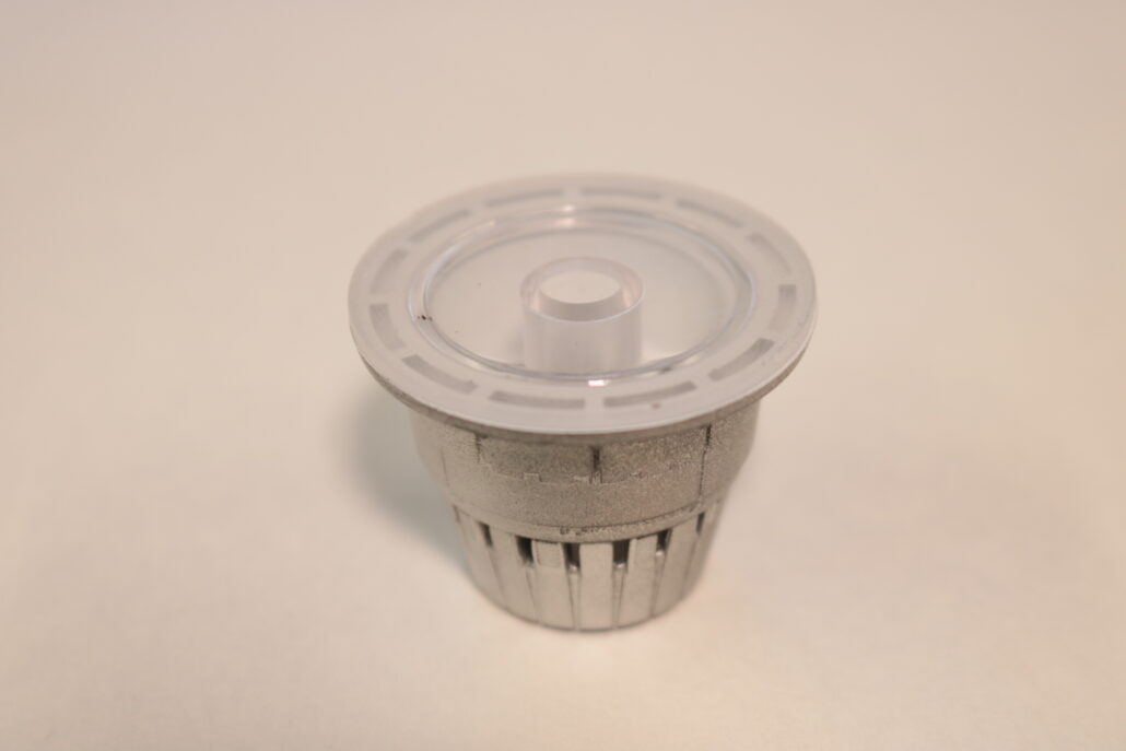
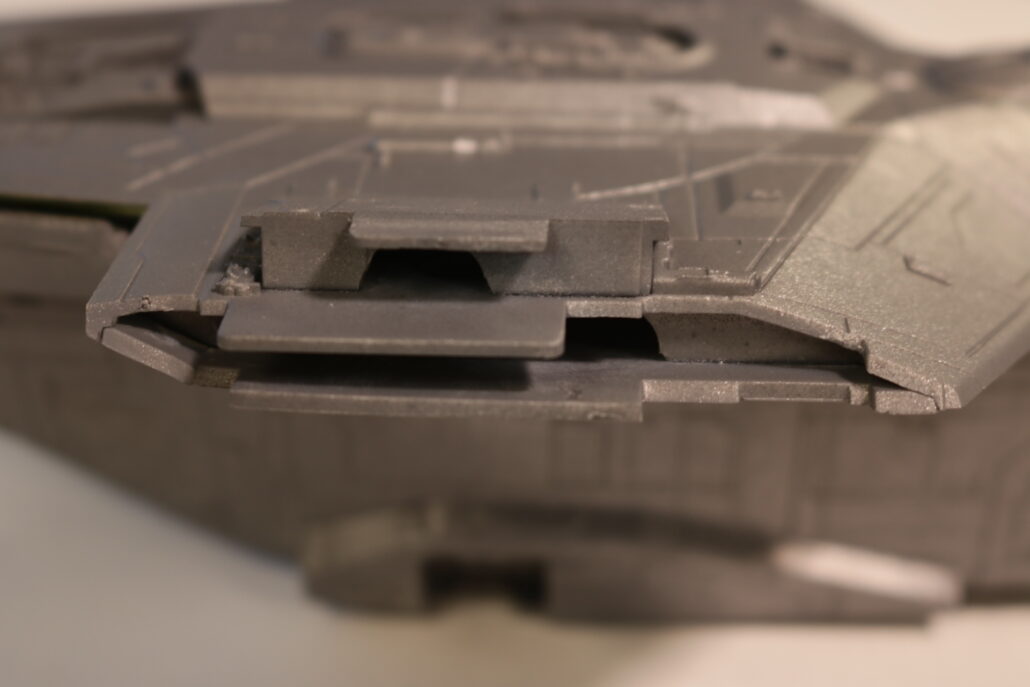
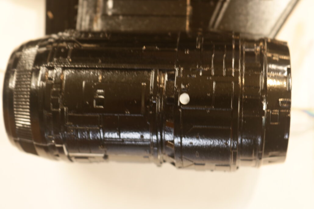
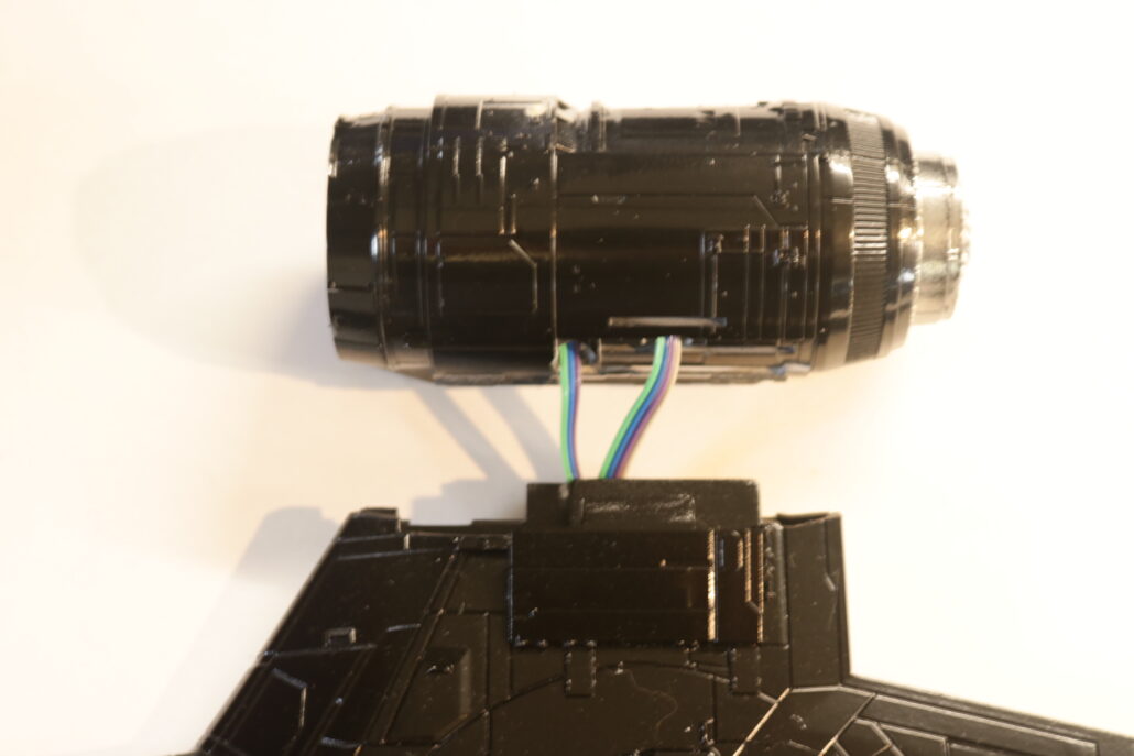
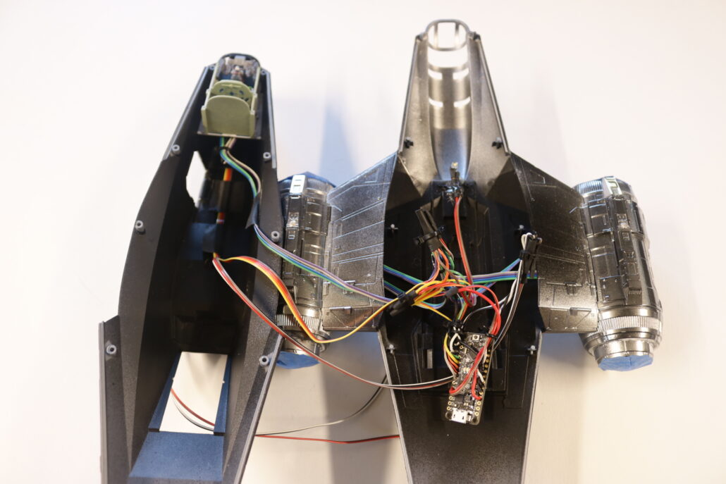
Engine Close Up & Mount
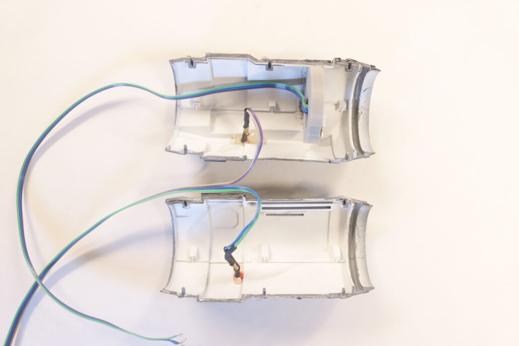
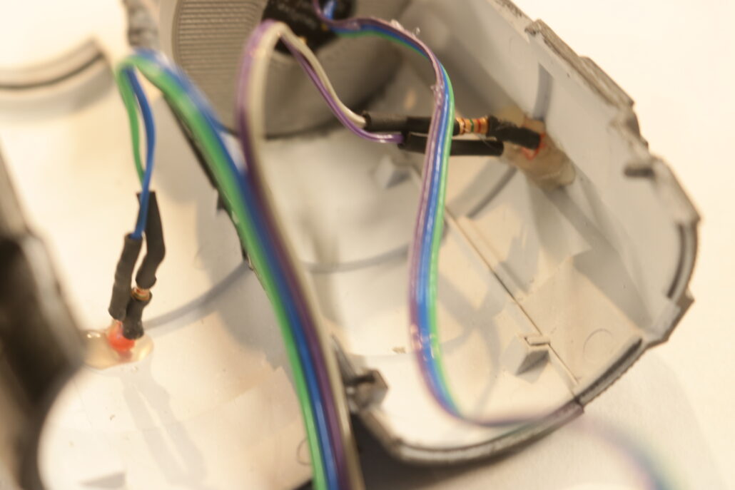
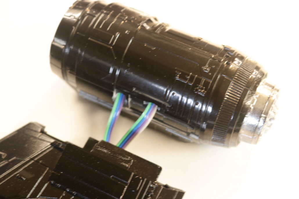
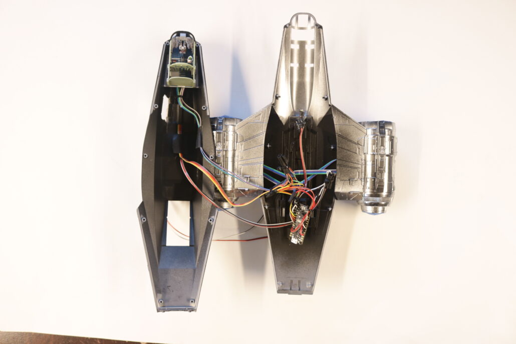
After setting the engine display boards & testing all the lighting you can fit and mount the engines on the wings. You want to pay close attention to wires well fitting these parts together and closing up the model. Its best to run all the bulk wiring to farthest point, the rear cargo door. Running the wire out of model will give you great access to soldering all the leds up to the board. Test ever contact point before closing any access to the circuit board or wiring.
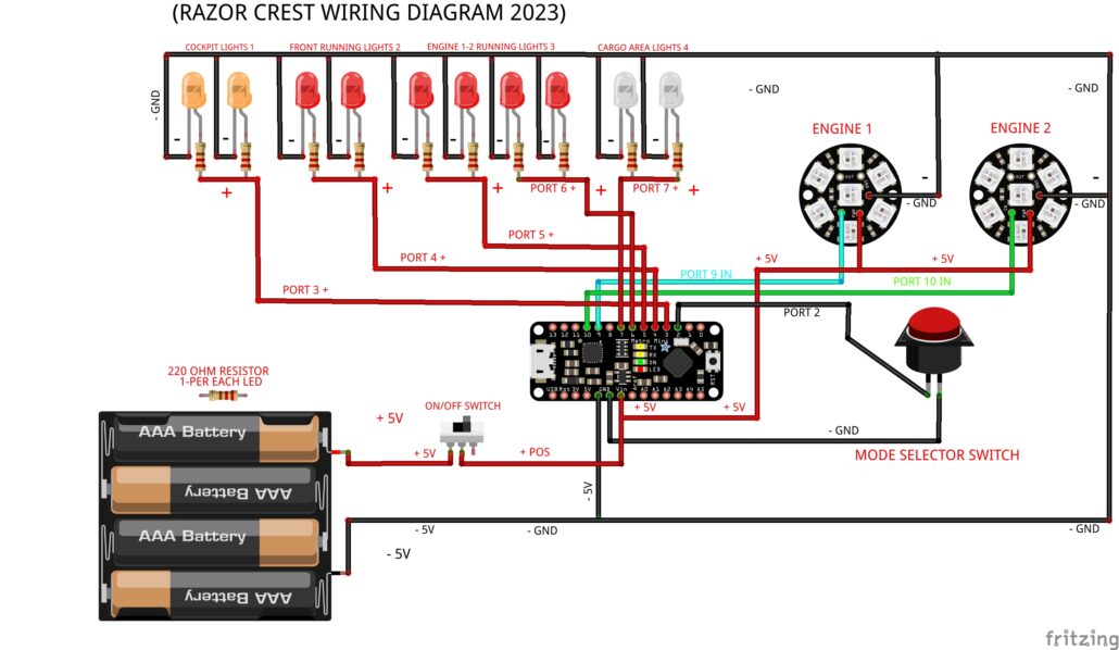
Wiring Diagram
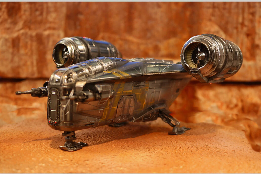
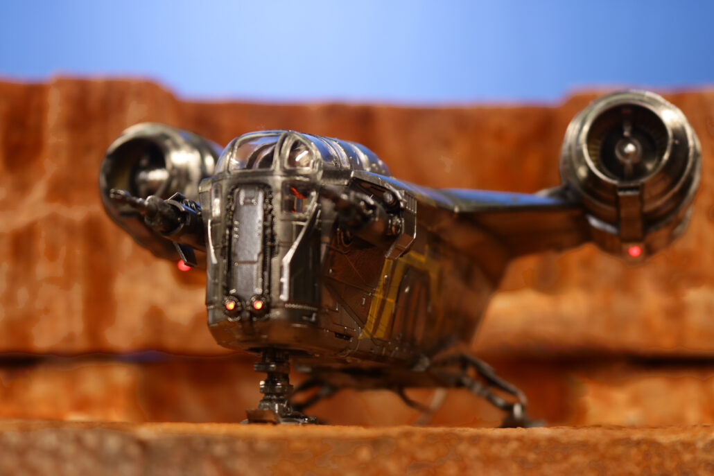
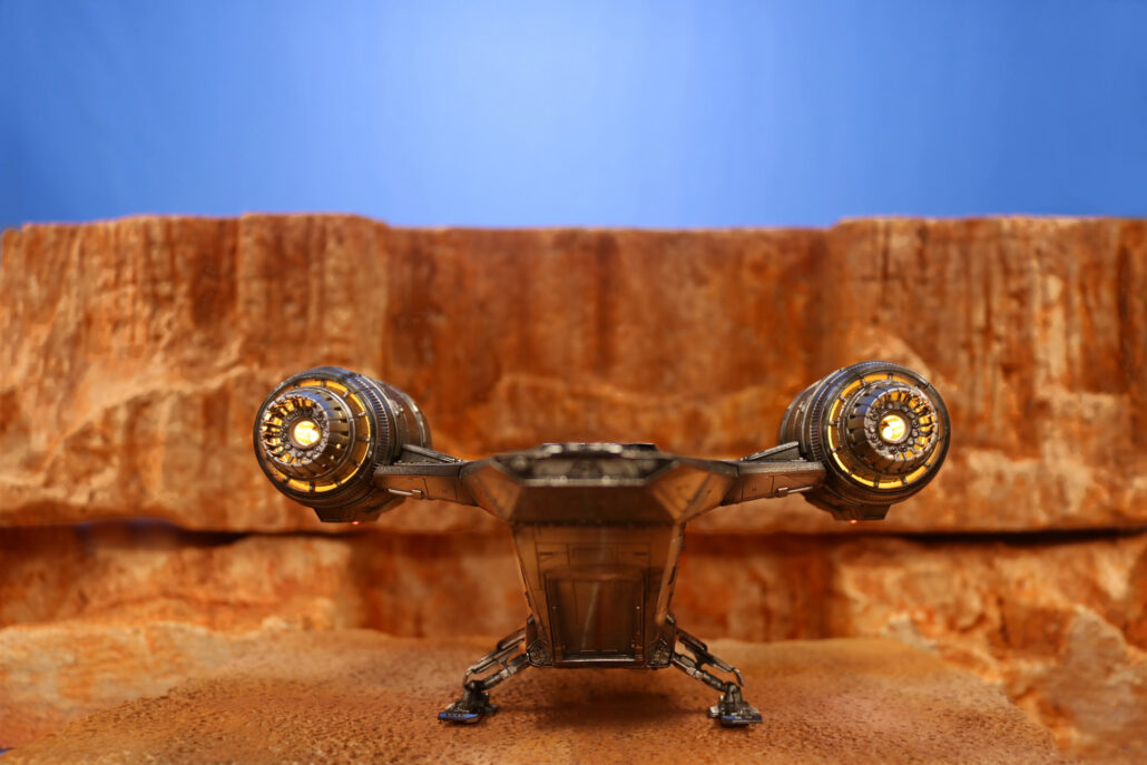
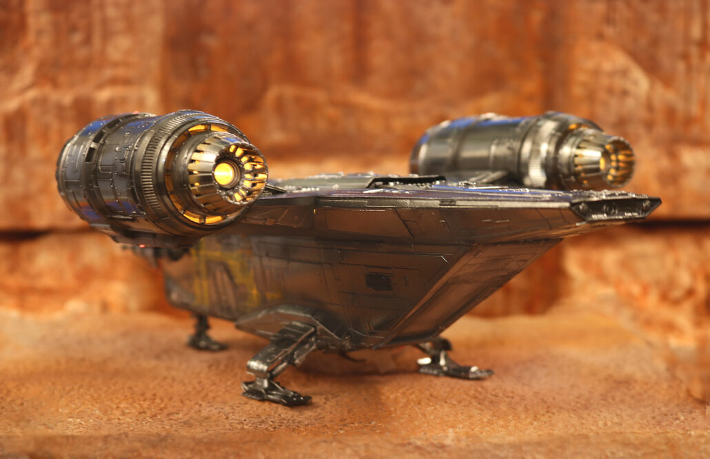
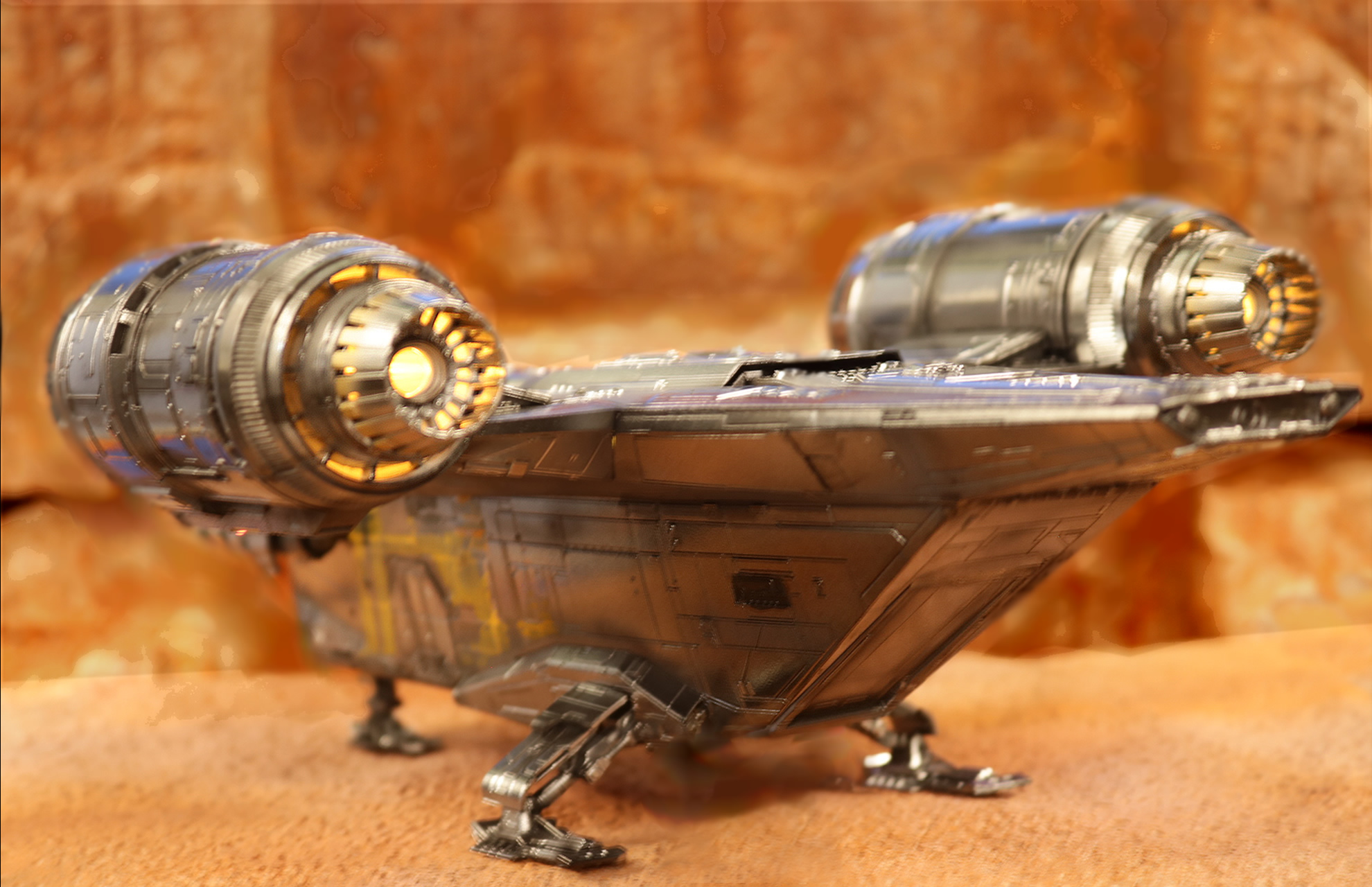
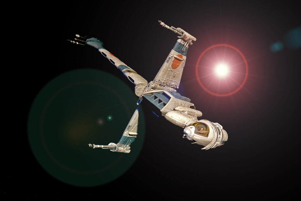
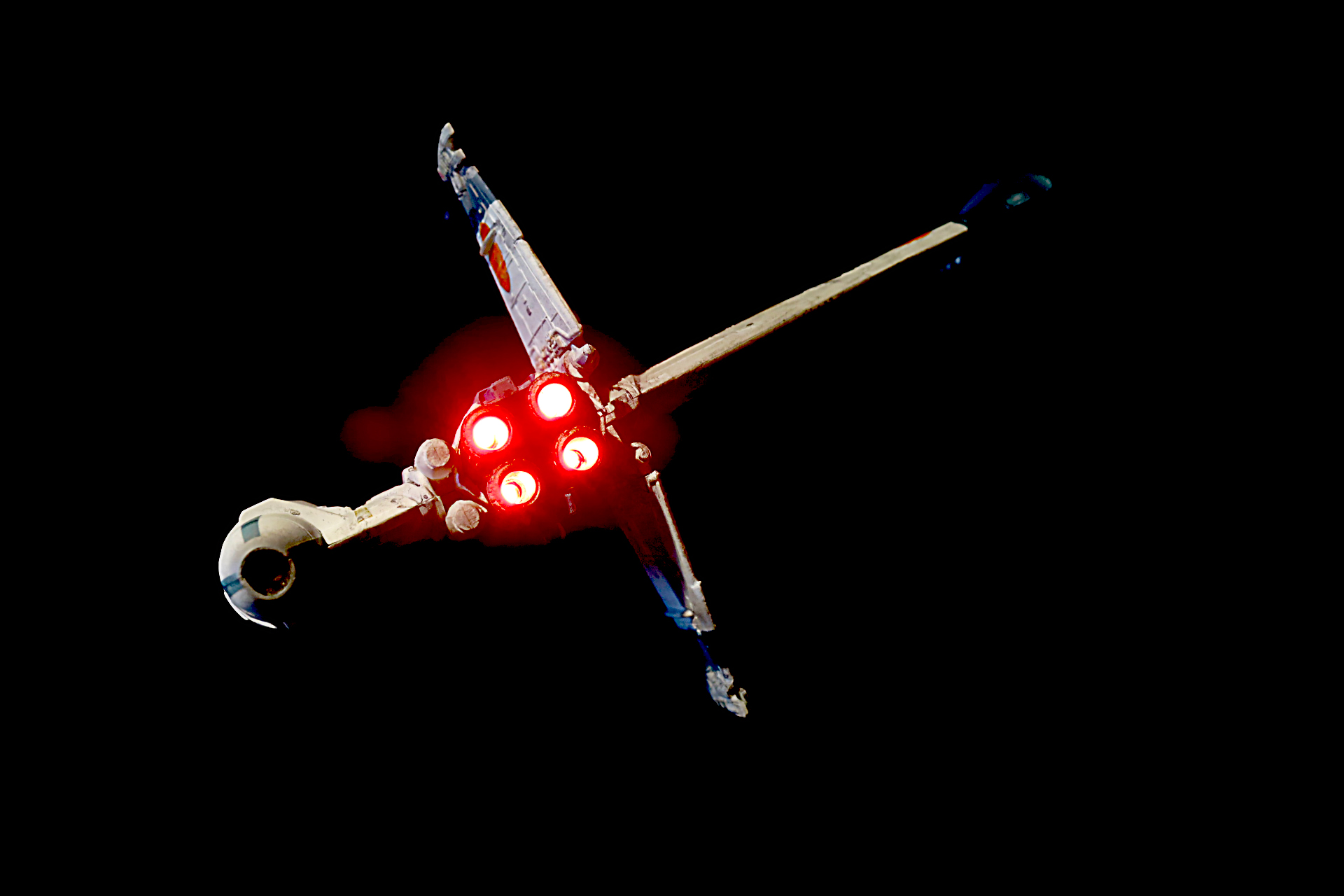
Finished Photos