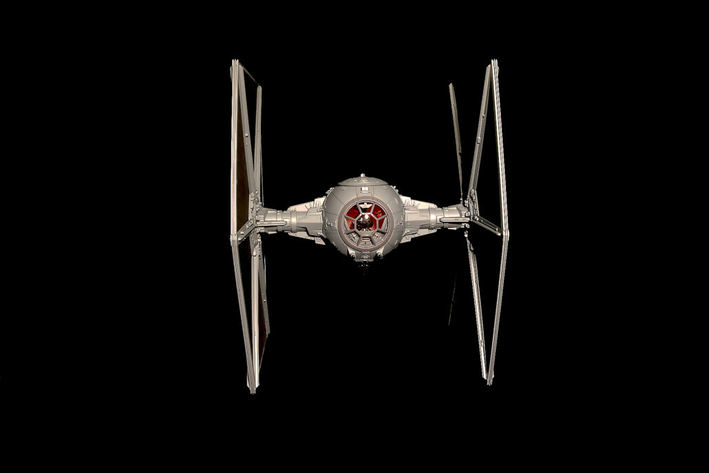
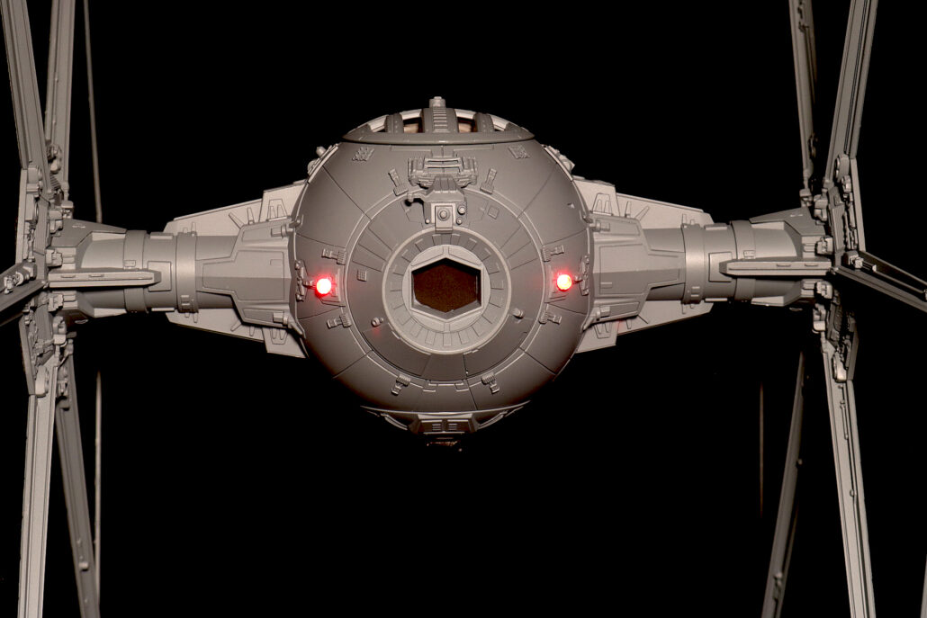
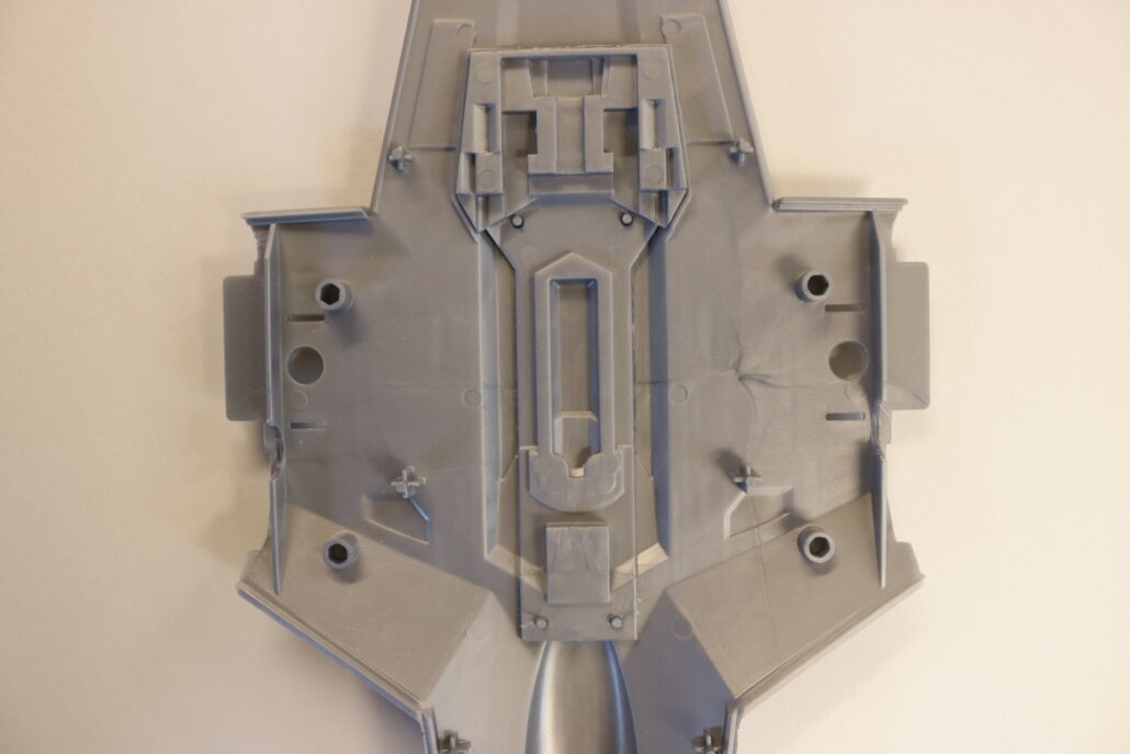
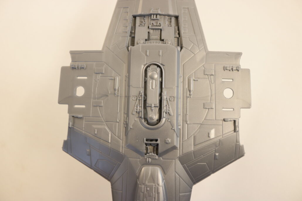
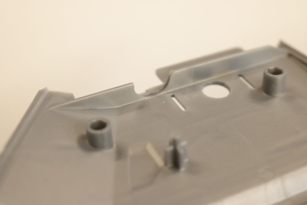
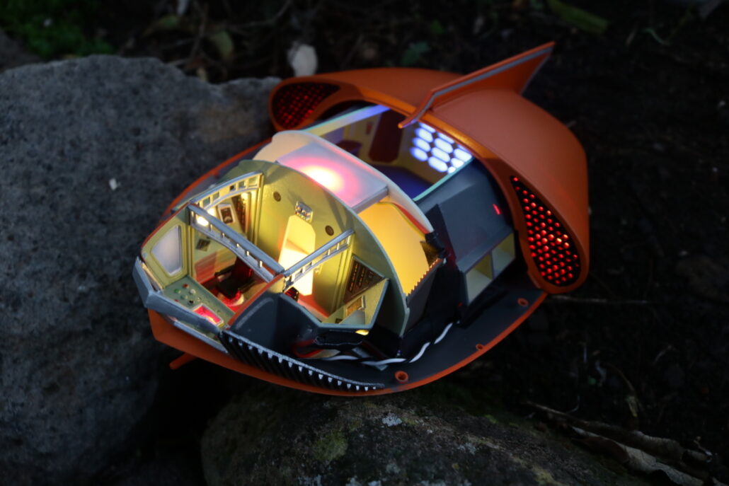
Unpacking the electronic parts kit, read all documentation & study diagrams. It is also good practice to have your own research material prepared before starting the lighting process. Start by reviewing all the model kit parts, get a general idea of how the model will come together. We will break down the model into two categories: on lighting – effects lighting. The main body comes in an front & rear body half’s. When setting up for the electronics, you will need to build the lighting into the rear half of the body after the main interior cockpit is inplace. The final result will be fewer wire connections as possible between the front & the rear half’s of the body. Pre build, paint & mount leds as you move through the model construction, testing lighting as you go
On Lighting:
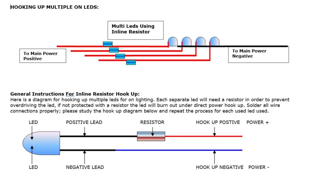
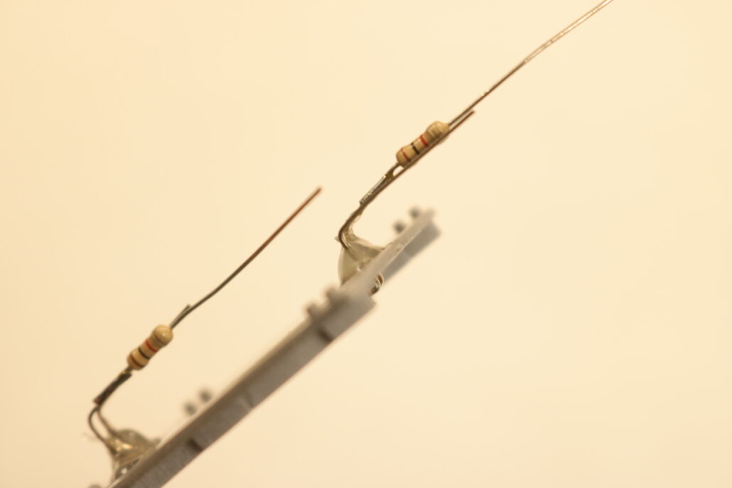
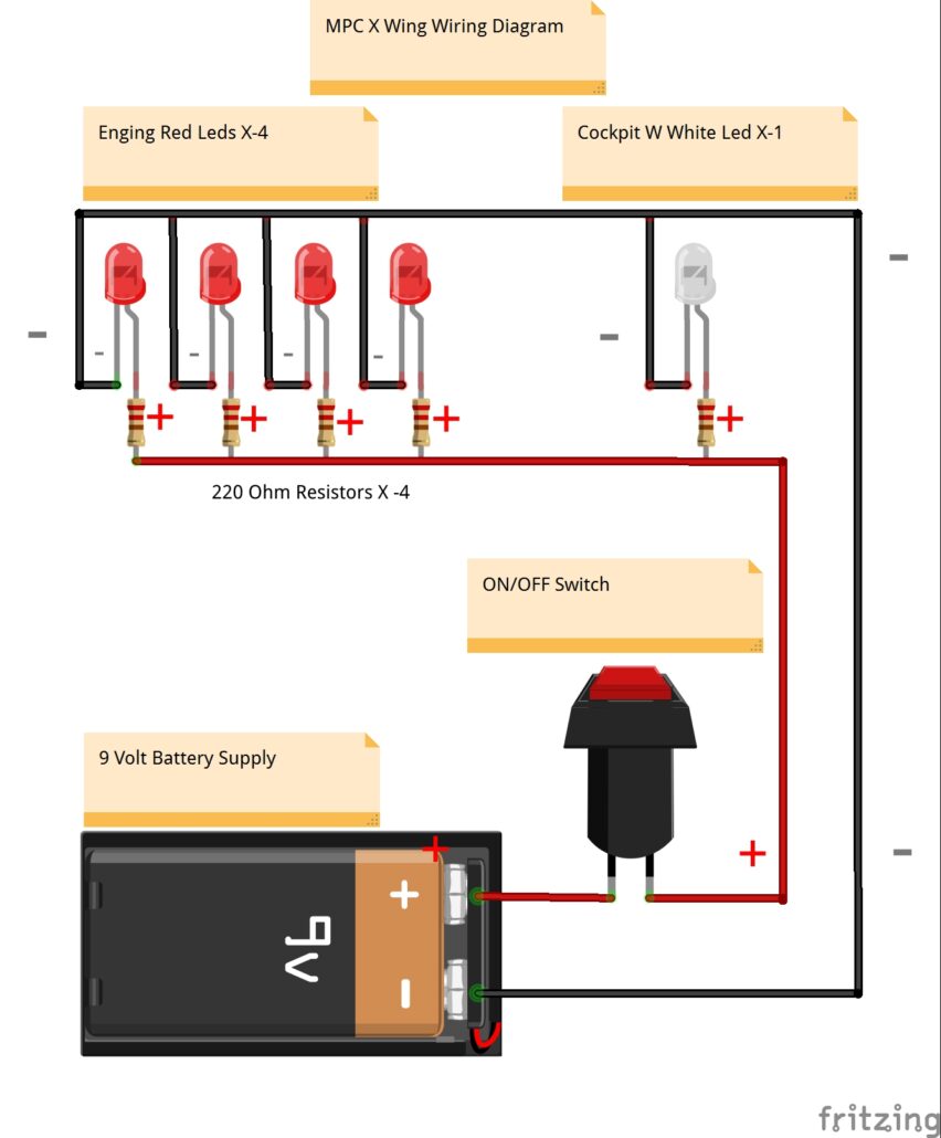
All the leds will use the in-line resistor set up, refer to the diagrams. When using this configuration, you have the choice of resistor to choose from to give different output levels for each led. Using the 220-Ohm resistor will give the brightest output within a safe operating range. Using the 1.5 K Ohm resistor will produce a dimmer output, giving you a much softer effect.
Circuit Board:
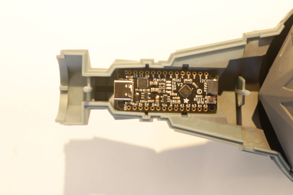
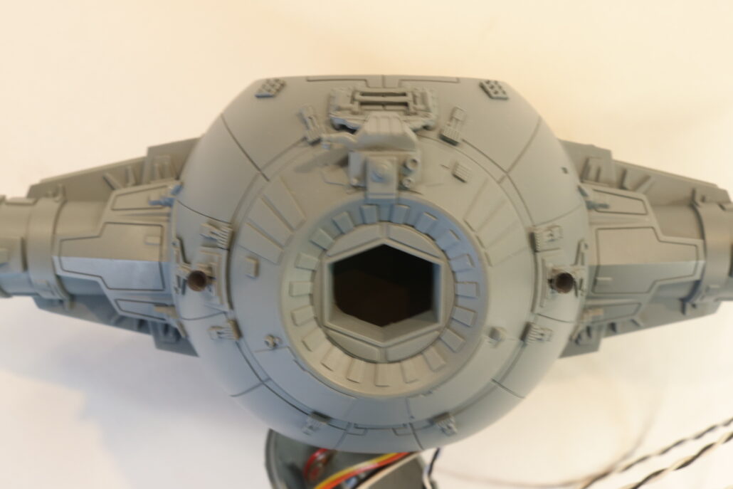
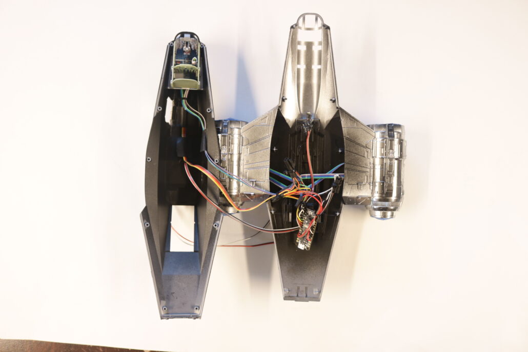
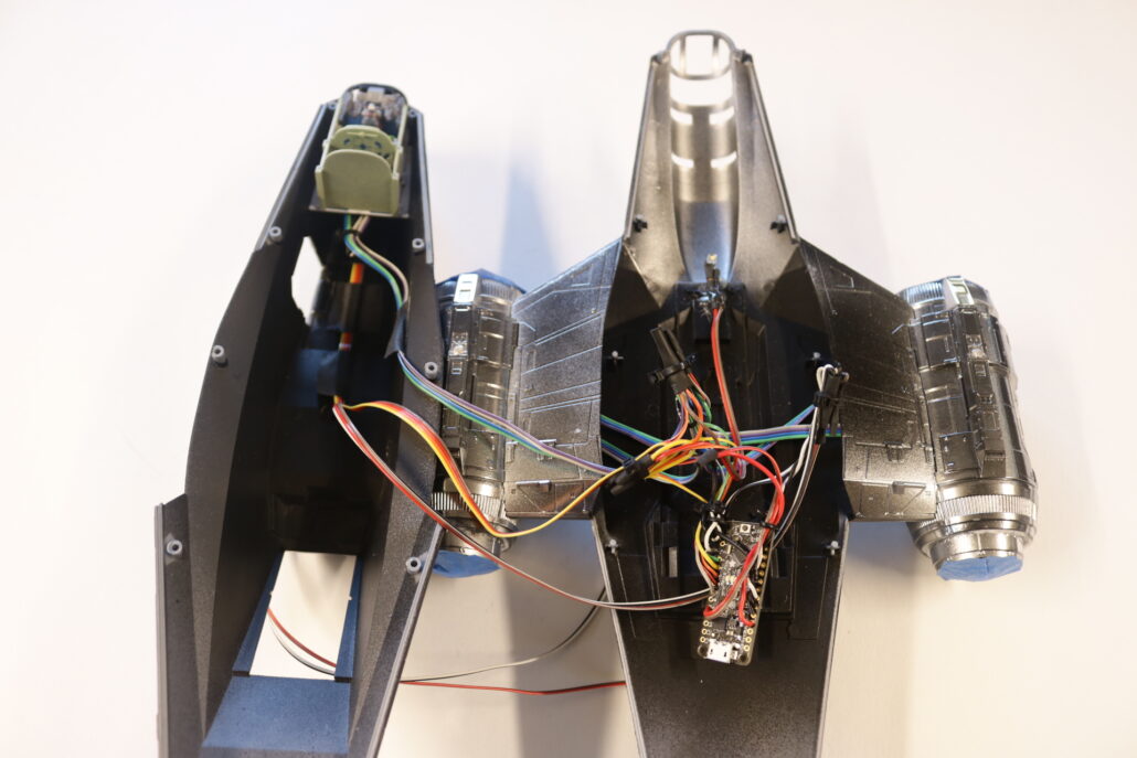
The main circuit board used to run all the lighting effect will need to be mounted in a wing strut cavity. This is the only space that you can mount the board with in the model, either side can be used & for those that want to access the USB C Port you will need to remove the end mounting pin & leave the wing cover accessible for hook up to the USB Port.
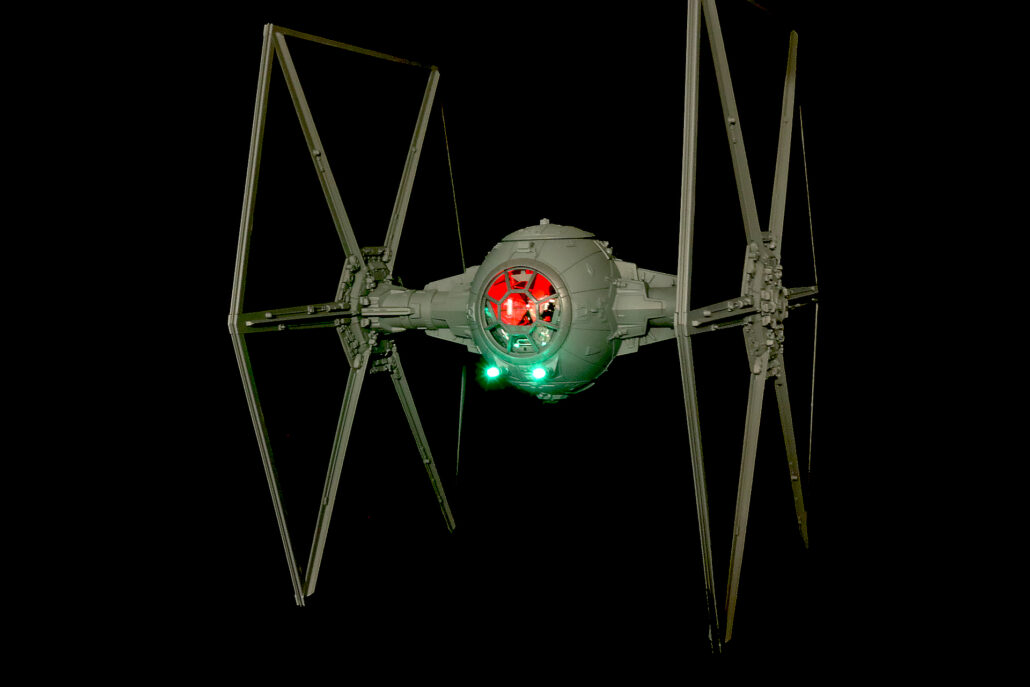
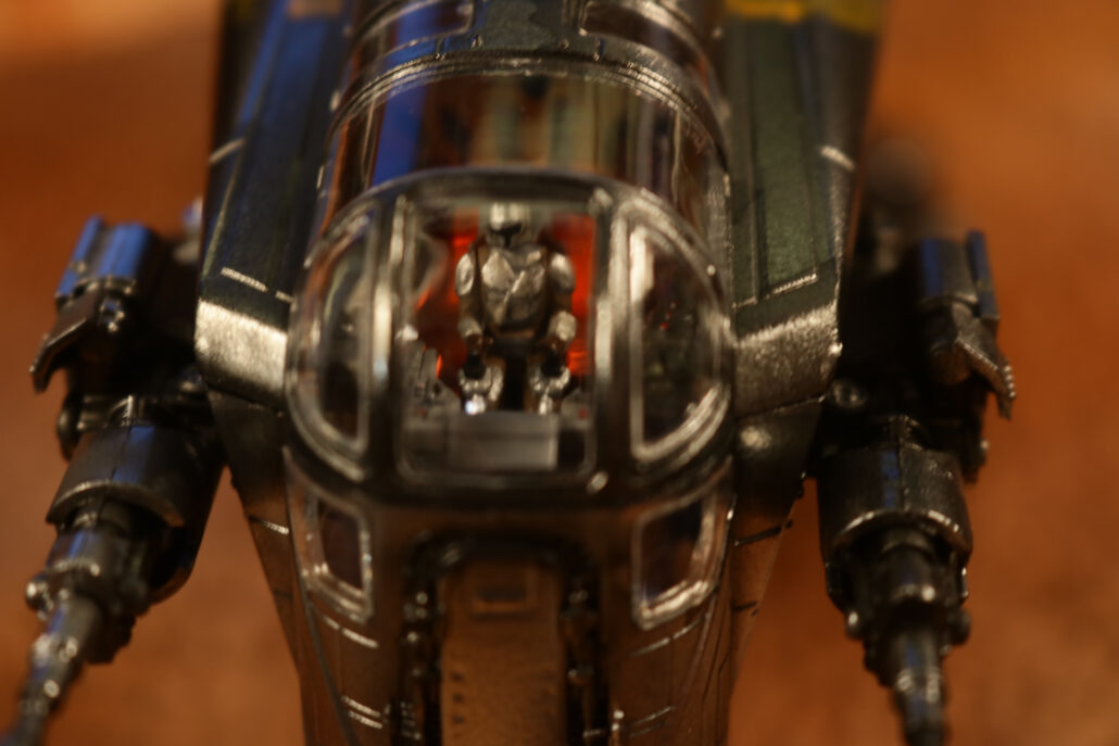
Cockpit Lighting:
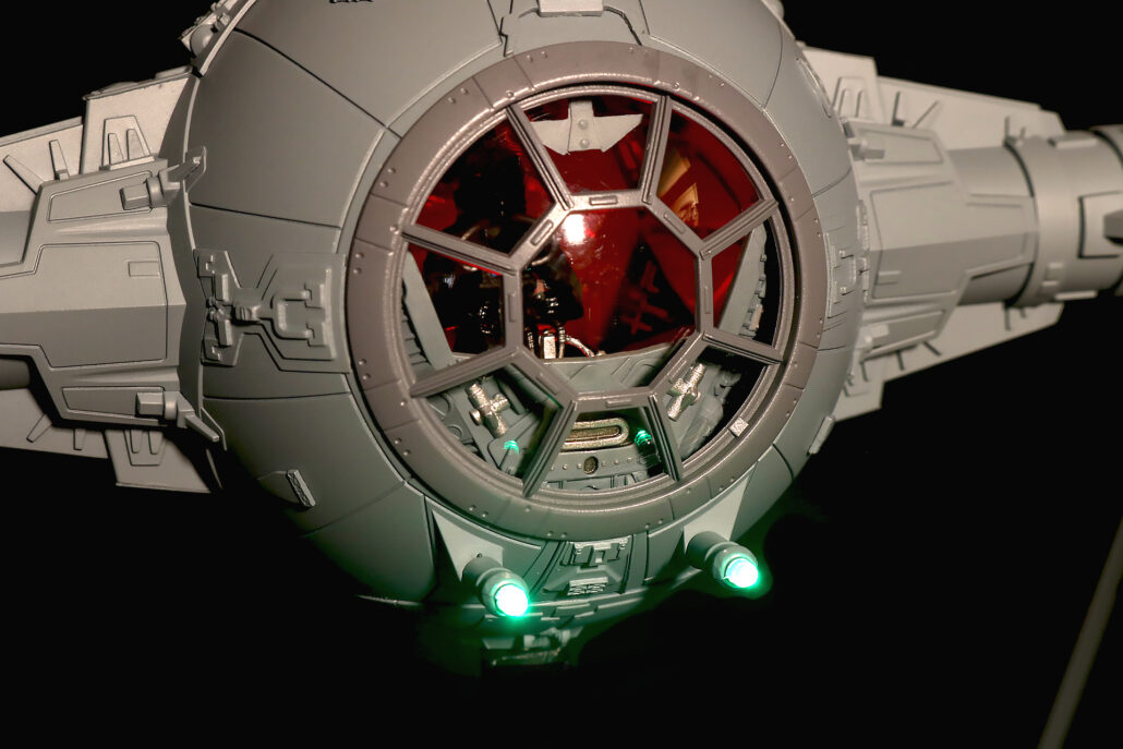
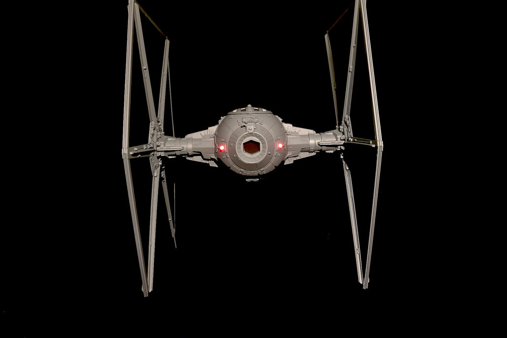
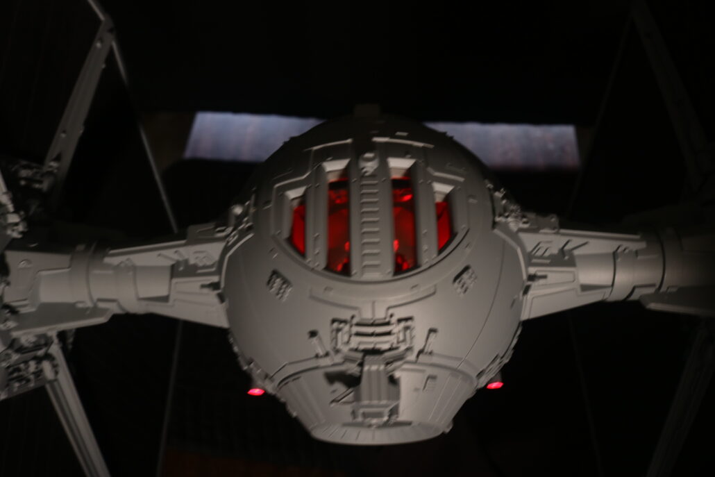
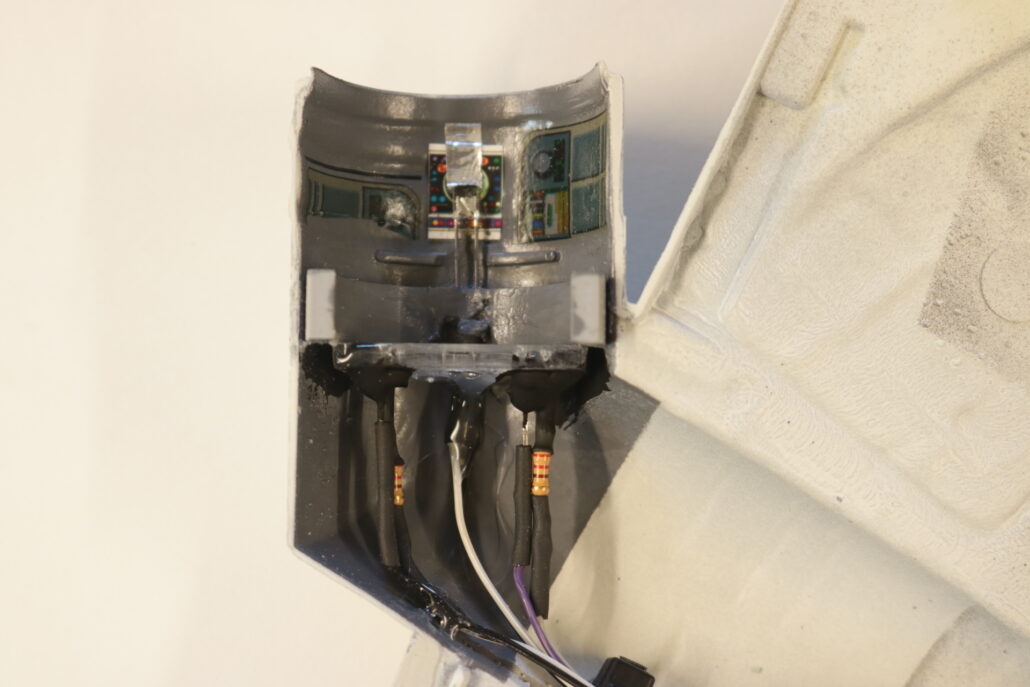
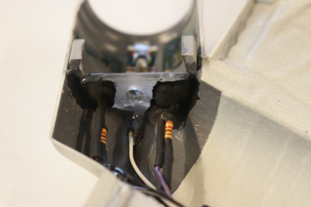
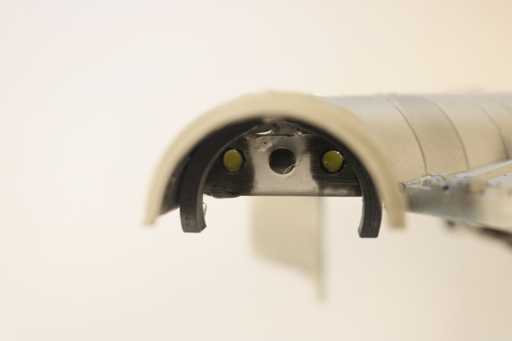
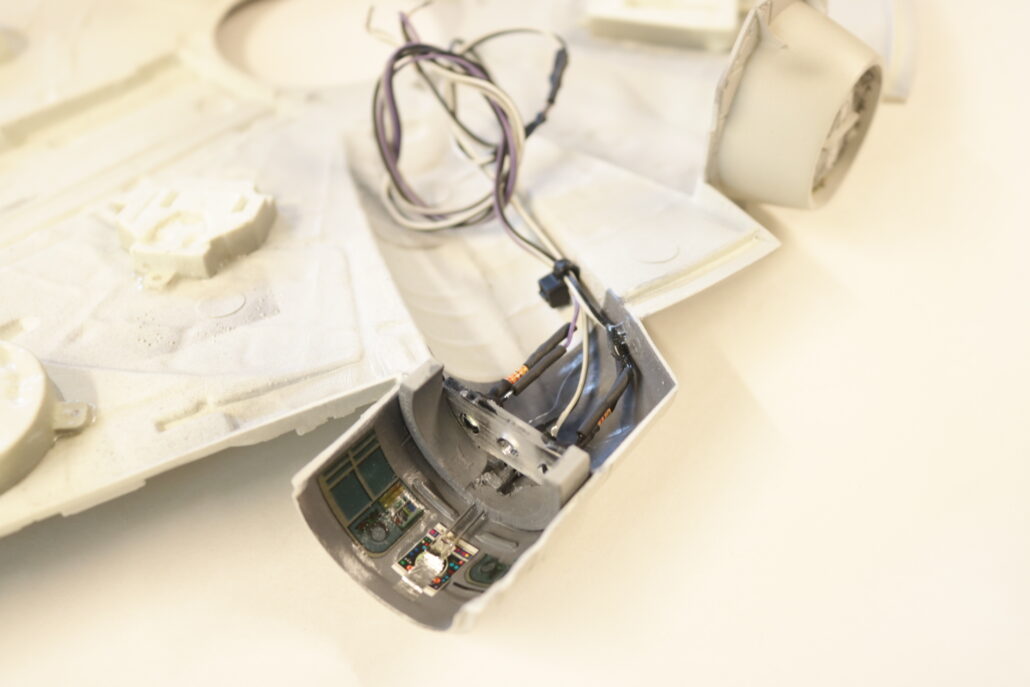
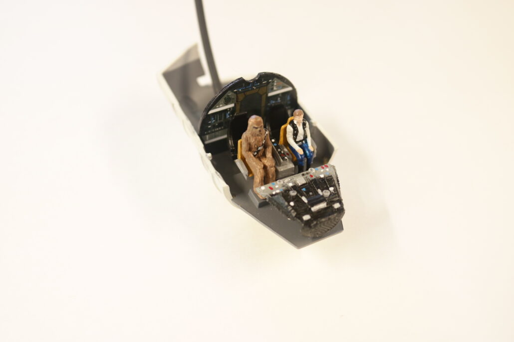
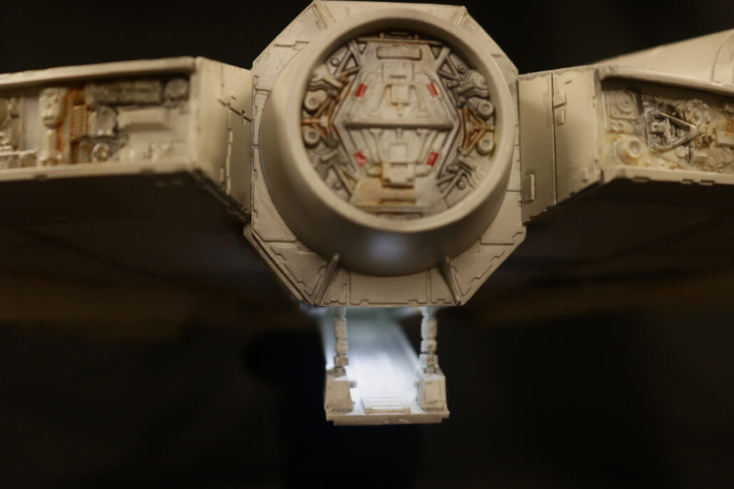
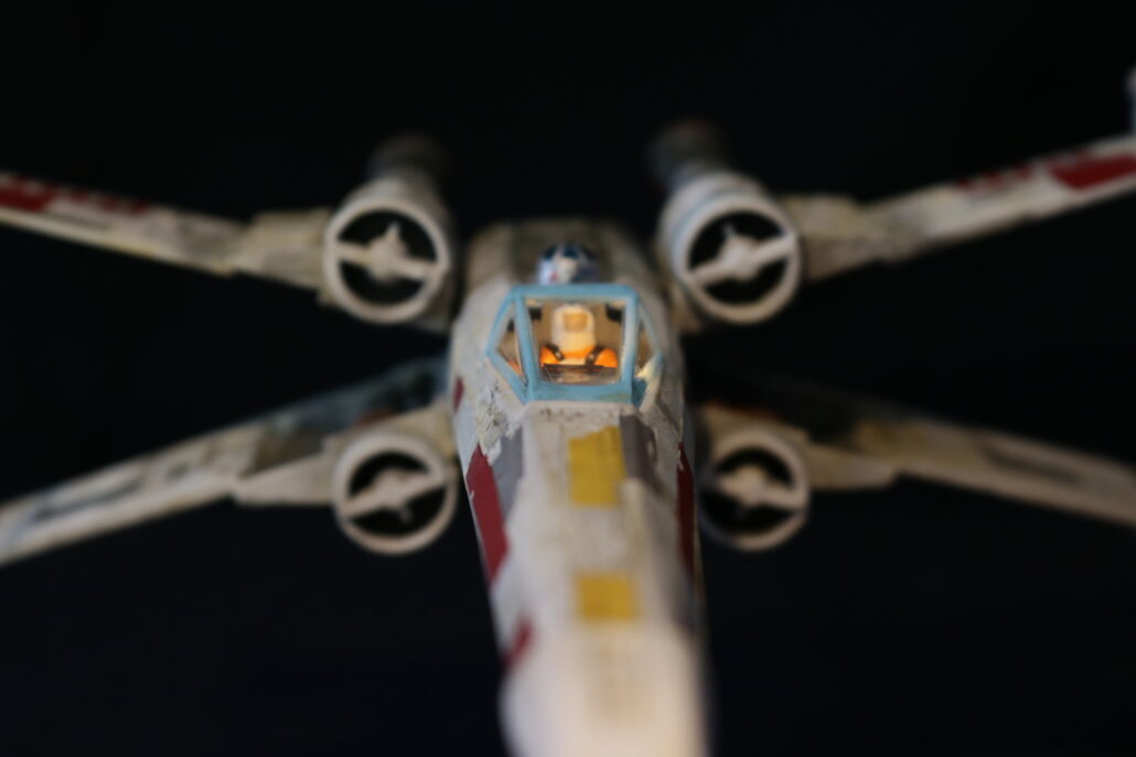
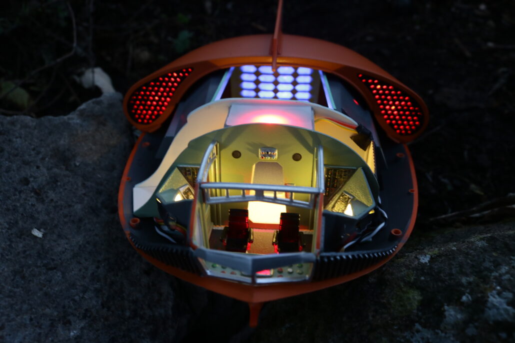
The interior cockpit area consists of a two red leds mounted in the very bottom of the mounting rod area. The two red lights are mounted on either side of pilots seat, looking upwards through the clear floor part. You will be using the inline resistor system for each leds used. Light block where need. Pre-built & paint where necessary.
Cockpit leds used are X-2 R 4.8mm wide leds mounted in the bottom of the mounting rod aera. Use 220-ohm resistors & connect to circuit board ports 2-7
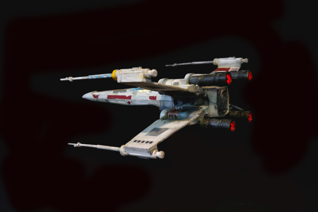
Lasers Cannons:
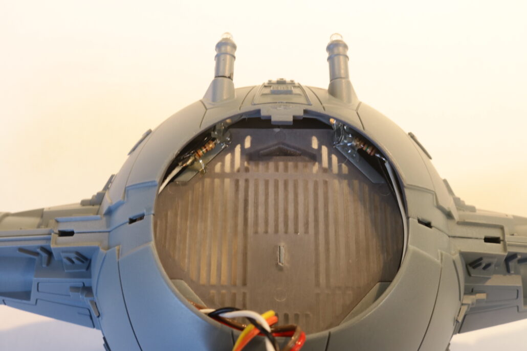
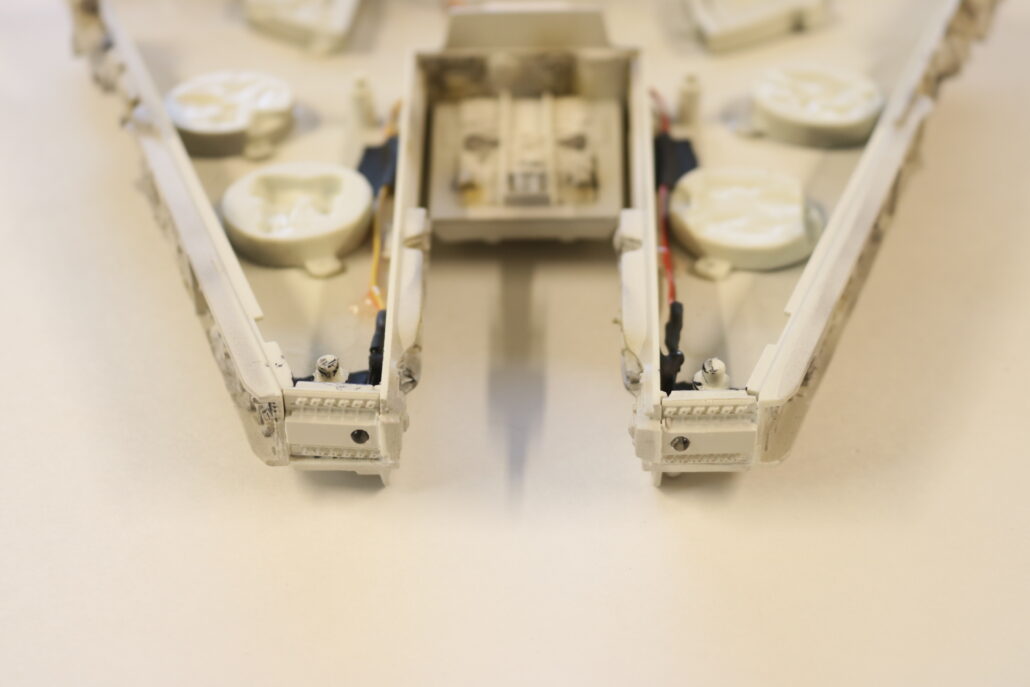
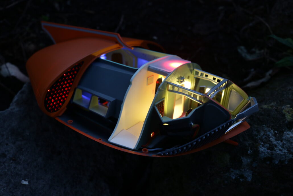
On the front of the ship there are 2 clear laser cannons in clear. These clear parts will need to be taped off or protected on the end tips & the very back where the leds will but against the back of the clear part transfering the light to the end of the tips. Use the X-2 green leds with the 150-ohm in line resistors set up. Connect to circuit board ports 8-9 fro laser cannon effect. You will need to slightly bend the leds & wire’s closer to wing strut so they are not seen by the red floor lights.
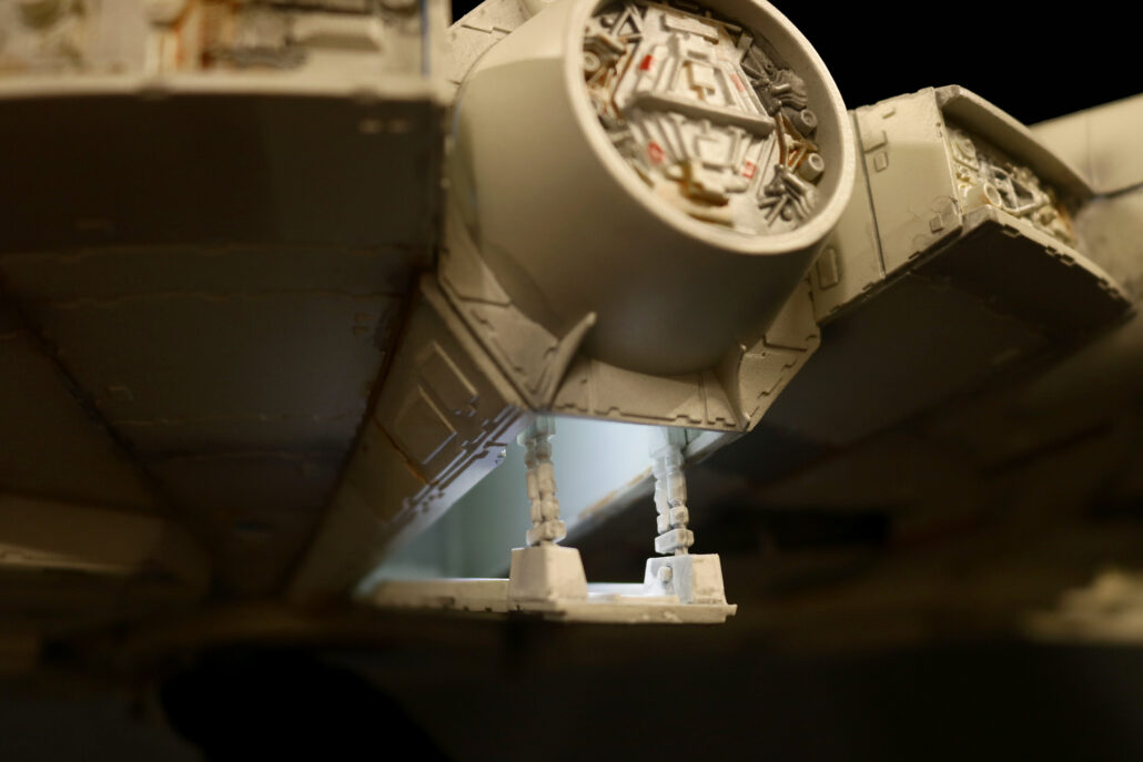
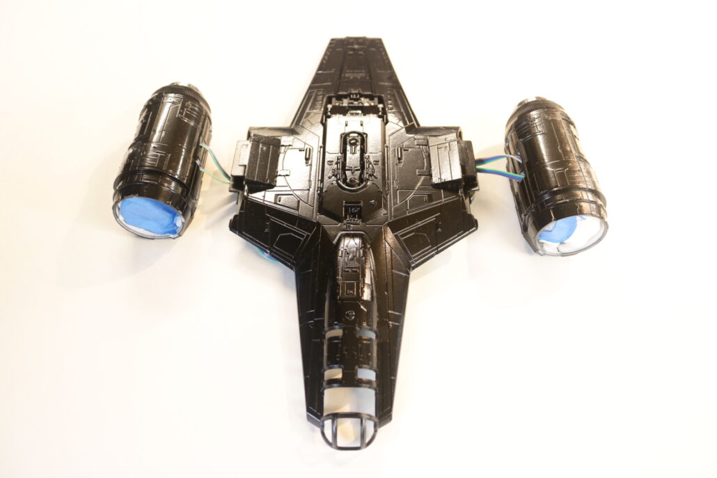
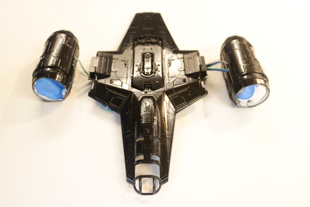
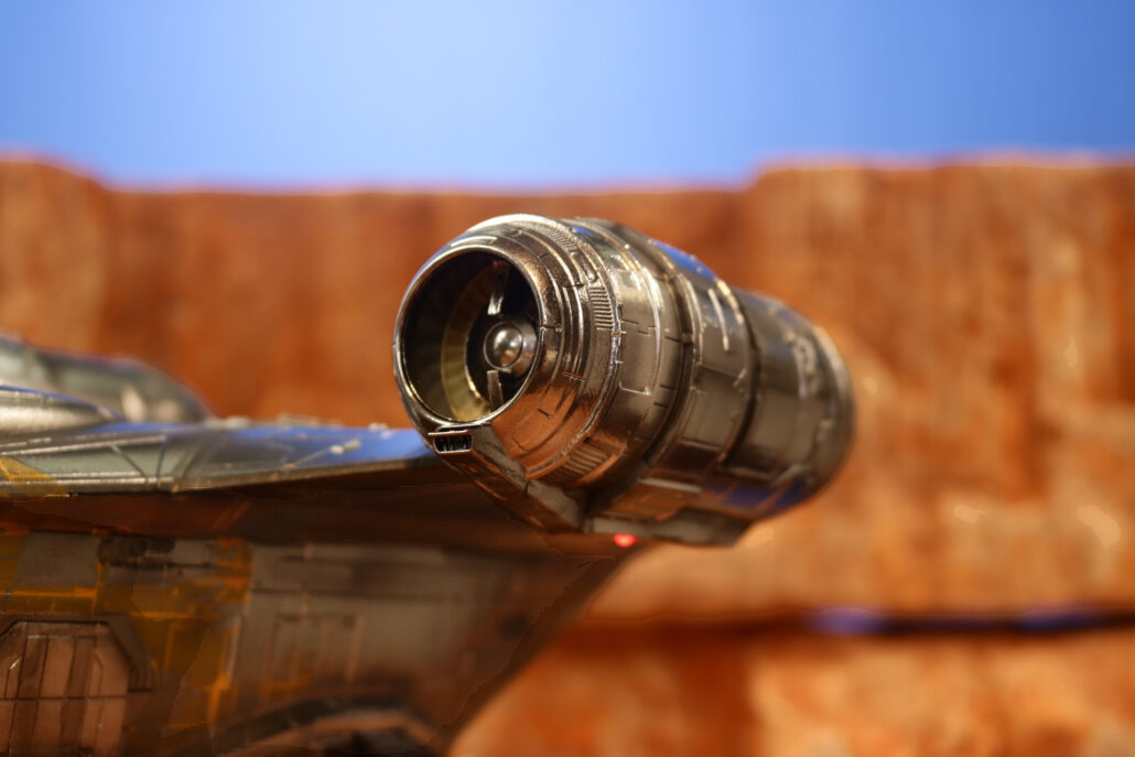
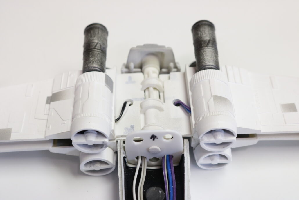
Engine Lighting:
The two rear engine lights will be mounted on the back side of the rear main body. You will want to pre light block & mount the clear lens parts in place before installing. The leds will need to be pre fitted in place before you put the interior cockpit inside the rear half of the model. This is a very tight fit & might require some sanding & trimming of the cockpit corners to allow a proper fit of the cockpit interior. The red leds will need to be slightly bent towards the wing strut since the fit is so tight. Use the 220 ohm inline resistor set up for each leds & connect to ports 10-11 on the circuit board.
Unpacking the electronic parts kit, read all documentation & study diagrams.t is also good practice to have your own research material prepared before starting the lighting process. Start by reviewing all the model kit parts, get a general idea of how the model will come together. We will break down the model into two categories: on lighting – effects lighting. The main body comes in an upper & lower body half’s. When setting up for the electronics, you will need to build the lighting into the main body as a pseudo separate lighting system. The final result will be fewer wire connections as possible between the two main body parts & the rear engine assembly. Pre build, paint & mount leds as you move through the model construction, testing lighting as you go.
On Lighting:
All the leds will use the in-line resistor set up, refer to diagrams above. When using this configuration, you have the choice of resistor to choose from to give different output levels for each led. Using the 220-Ohm resistor will give the brightest output within a safe operating range. Using the 1.5 K Ohm resistor will produce a dimmer output, giving you a much softer effect.
Cockpit Lighting:
INTERIOR COCKPIT:
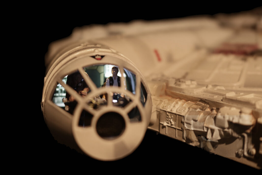
The interior cockpit area consists of a two white leds back lighting cockpit clear wall panel. You will be using the inline resistor system for each leds used. Tape off the backside of clear cockpit, apply decals as directed to the face side. Light block where need. Pre-built & paint where necessary.
Cockpit leds used: X-2 W 4.8mm wide leds mounted mid-way on each side of the clear back wall. Use 220-ohm resistors.
INTERIOR COCKPIT CONSOLE:
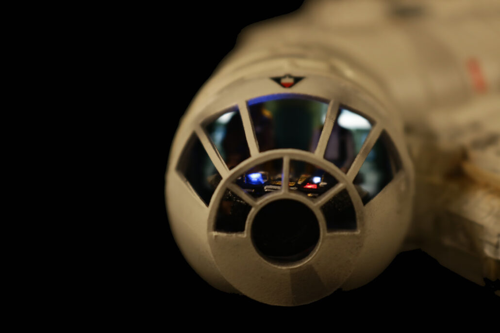
The interior cockpit area has a series of fiberoptic that can be used either on a scratch-built console or cockpit back wall. There are three zones, one is a fast blinker, one is a slow blinker & one is for on steady lighting. Use the inline resistor system to power each leds used. The kit comes with 9/32 tubing that will house these three lighting combos. The fiberoptic wires can be routed through the back wall or routed through the cockpit floor area.
Cockpit Leds used: X-1 R W5.0mm, X-1 B W5.0mm, X-1 W W5.0mm.
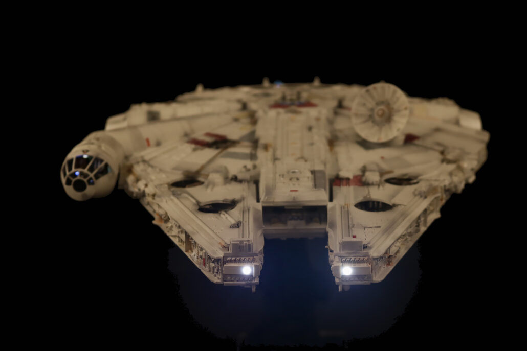
Head Lights:
The main front headlights will need to be drilled out for two 3mm leds using the inline resistor set up to power each led used. Please study the wiring diagram. These are set up to have their own on/off switch controlled of the main power source after the main power cut off switch.
Head Lights Used: X-2 W 3.0mm. Use 220-ohm resistors.
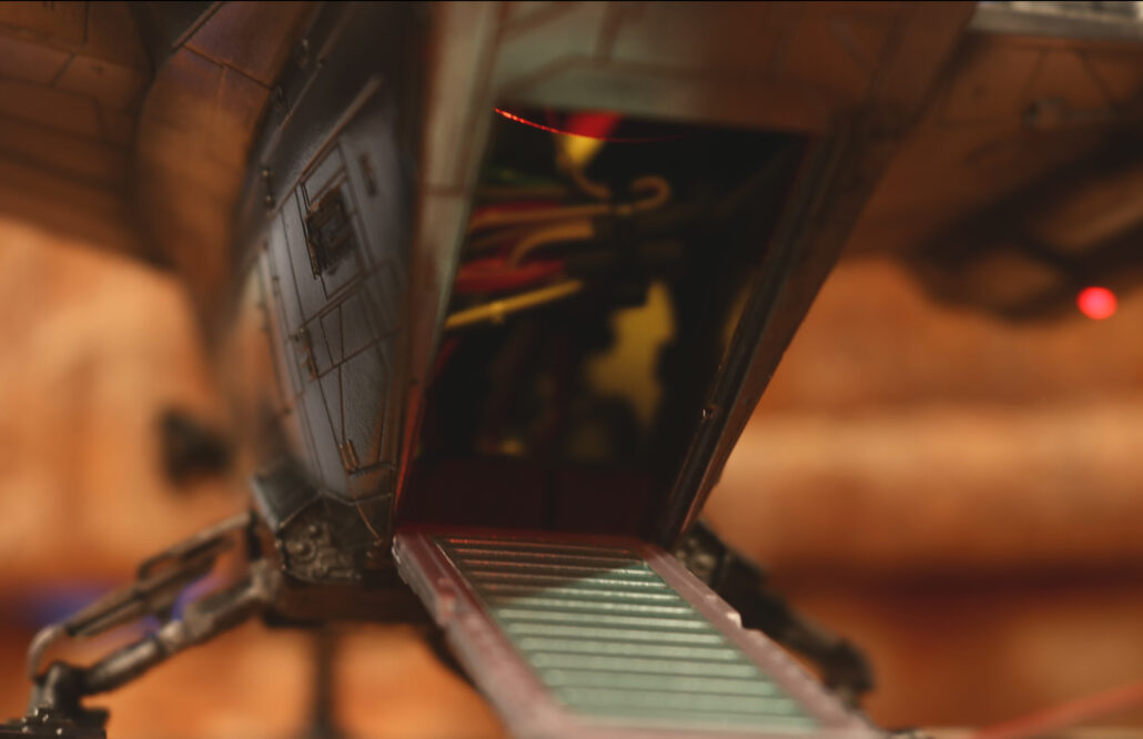
Passenger Ramp:
The passenger ramp consists of one led mounted in the mid upper roof area of the ramp looking downwards. You will be using the inline resistor system to power each led used. You might want to tie the headlights to the same on/off switch used for the passenger ramp.
Passenger Ramp leds used: X-1 W 3.0mm. Use 1.5K-ohm resistors.
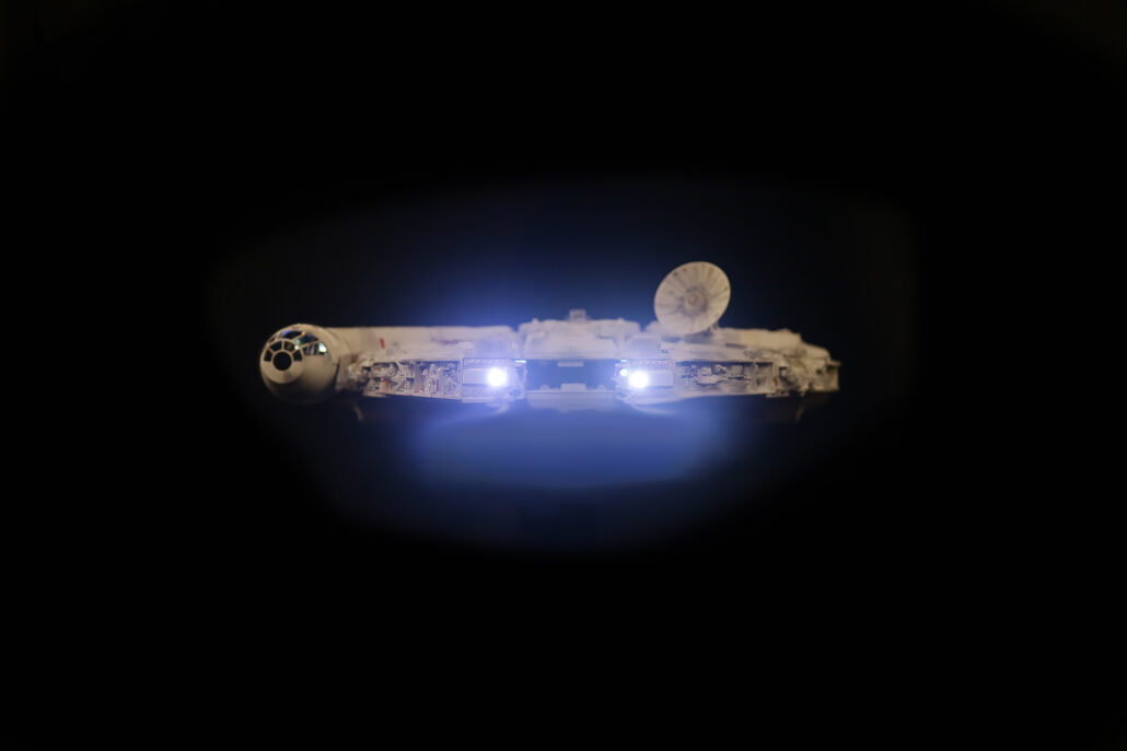
Engine Effect:
The engine used a RGBW strip to power the engine feature. You will need to construct a strip of styrene bent to the angle of the engine curve. The kit also comes with a diffusion material that will need to be cut to fit against the clear blue stock lens. The led strip has three pads, 5V+, 5V-, DATA IN. Data in will be hook up for port 9 on the controller board. There is also a switch port that will turn on the engine effect and cockpit lighting. Port 2 on the controller board controls the advancement of the effect. It is very important that you pay attention to the arrow on the strip that is flowing away from the fist point of contact. No inline resistor is required for the strip & you can driver the main 5V + direct from the power source after the main on/off cut off switch.
First start by getting yourself familiar with all the model kit parts & where they are positioned to assemble the model. Second read all the information regarding the model lighting kit & wiring diagram. There are only a few modifications that will need to be made to the model before the lighting system install. This lighting system is more advanced & will require electronic knowledge.
Preparing The Body
One of the first steps is drilling out the main body to transfer wiring into the main body where the controller board is stored. The more passage ways you have for wiring the better, but keep in mind that you are transferring your holes with in the areas inside the model only.
Preparing The Engines
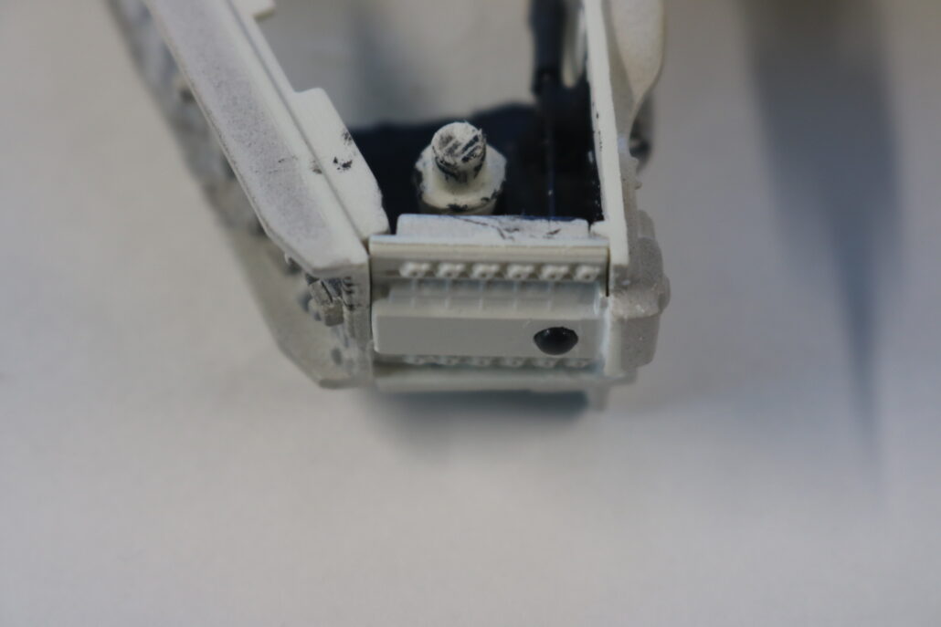
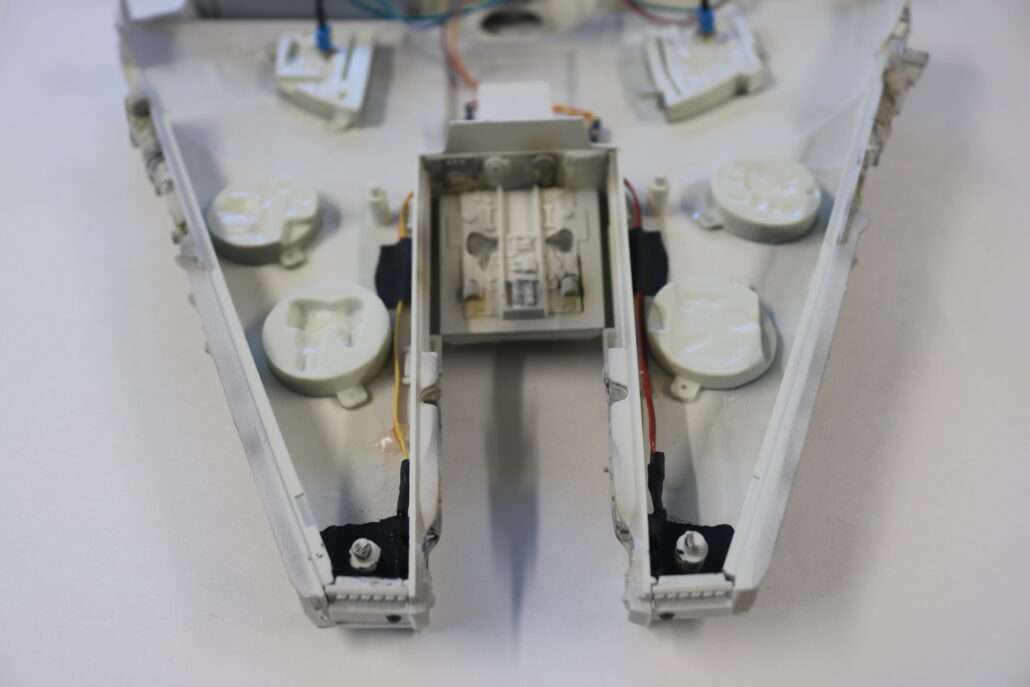
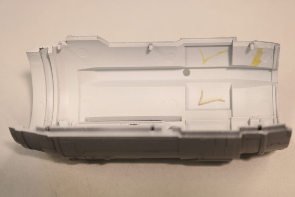
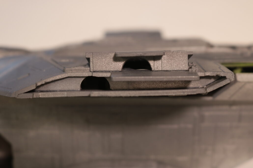
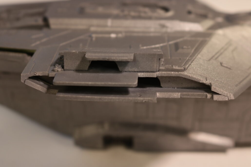
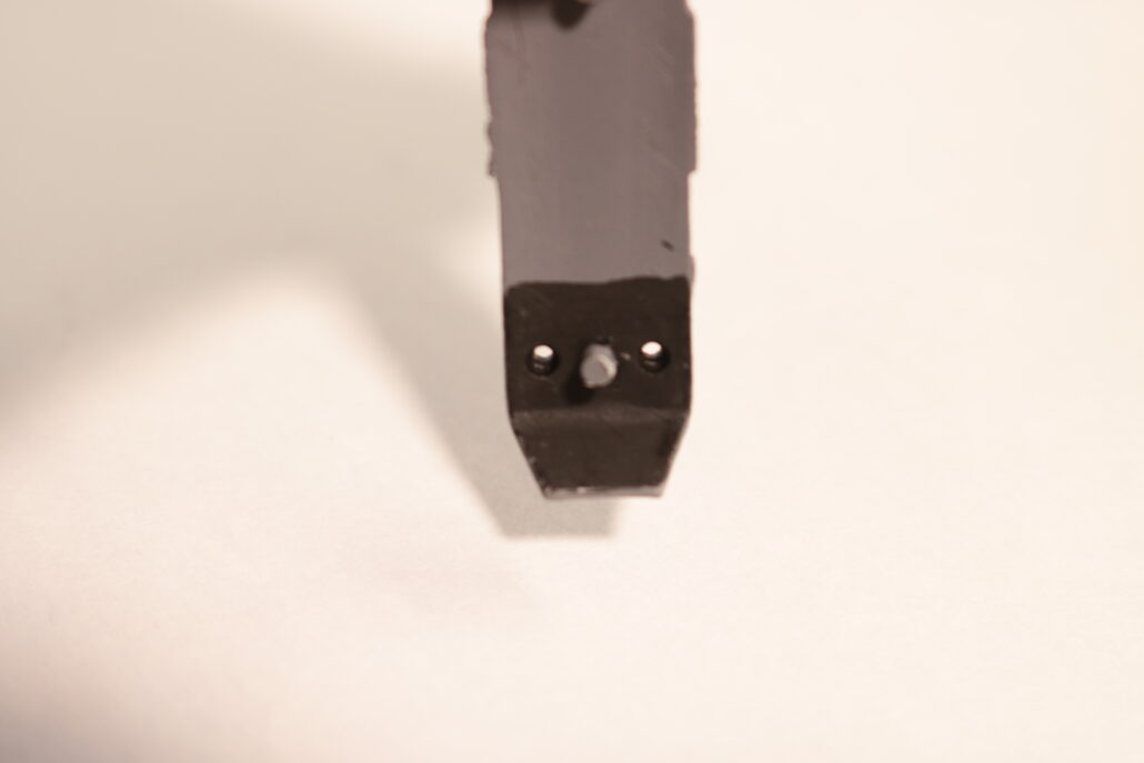
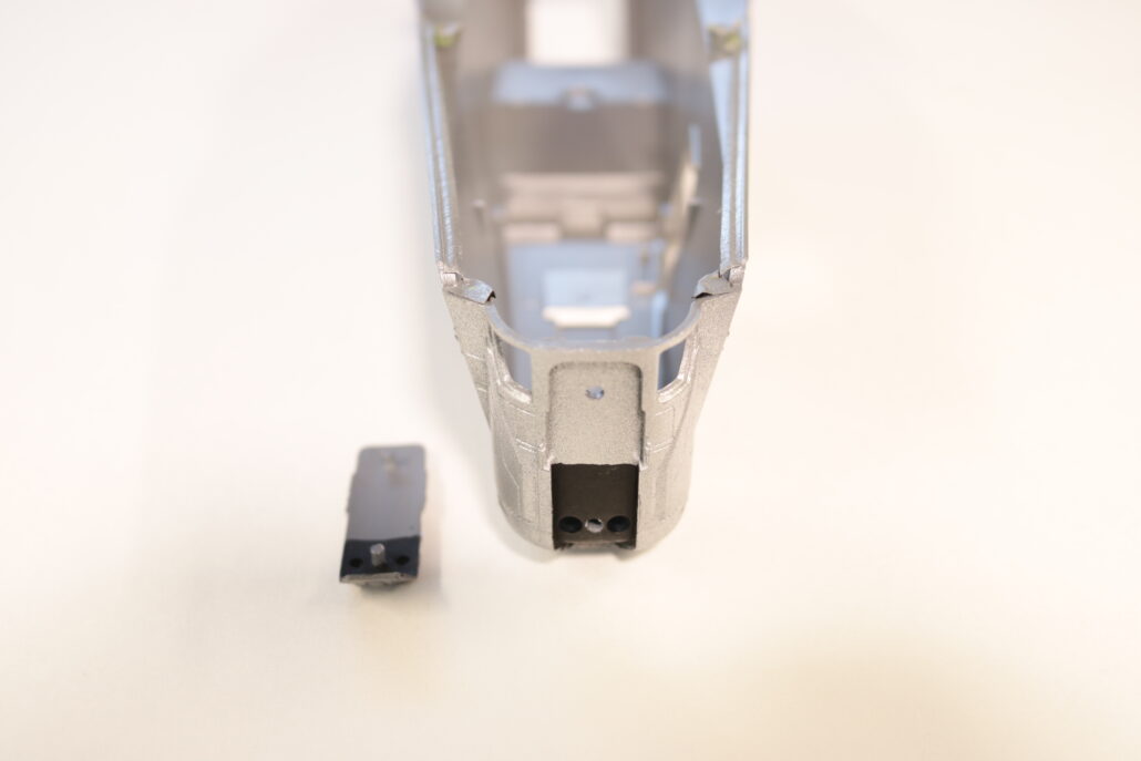
One of the second step is to cut out all the small rear engine shroud slots, I used a hobby knife & some super fine files. The next step there will need to be some porting in and around the engine nacelles. The upper engine mounting blocks will also need drilling & porting. I have added some free downloadable 3D files for internal engine display brackets (THE BRACKETS ARE NOT INCLUDED IN THE KIT) you will need to 3D print them or scratch build the brackets on your own. This also a good time to drill out for all the red diffused marker or position lights, there are two small pairs in the very front drill outs that need need to be made behind the front face part, you want to be careful not to drill all the way through with the 3mm drill bit. All the other marker or position lights are on the upper & lower areas of the forward section of the nacelle.
Cockpit
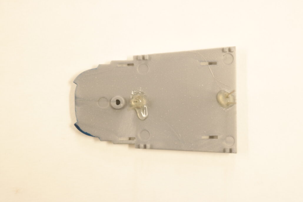
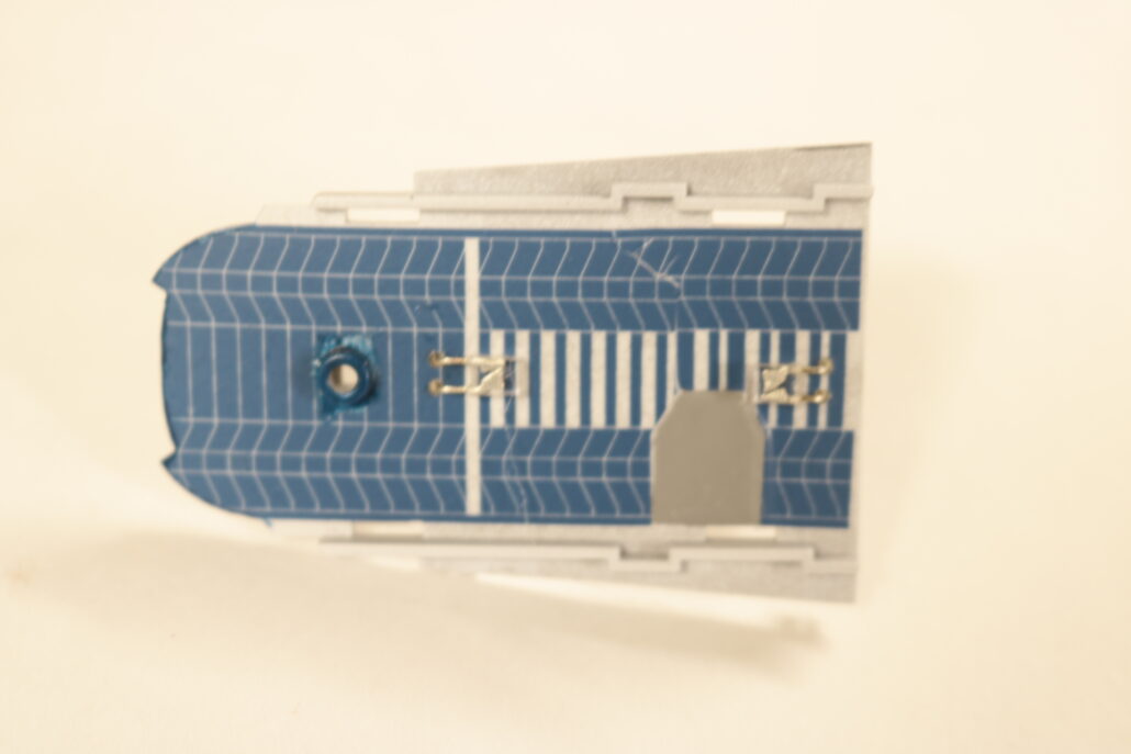
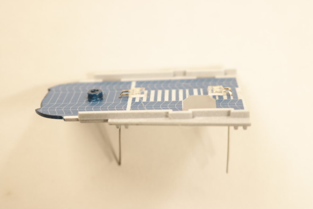
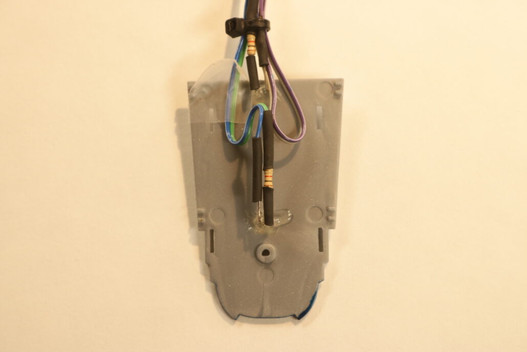
In the cockpit I took a floor lighting approach, by mounting two small square leds bent at a 90 degree angle flush mounted to the floor. There are two zones, FORWARD MAIN COCKPIT & AFT MECHANICAL ROOM. You will need to drill out with a #64 bit pinvise four small enough holes to send led leads through the floorboard. Its easiest to bend the led leads on the bottom side of the floor & solder your resistors, wire & shrink tubing. I prebuilt the floor with the leds mounted before I put the interior together and mounted it in the model.
Engine Display Boards
After all the parts have been almost 100% pre painted you can start figuring out the display bracket. This is also a good time to finish off the the rest of the nacelle marker lights & wire them in place. There are two ways of making the display brackets that hold them, A I give you the free stl file & you print them or B you scratch build the display holder. The free file for the bracket is on the order page.
Engine Close Up & Mount
After setting the engine display boards & testing all the lighting you can fit and mount the engines on the wings. You want to pay close attention to wires well fitting these parts together and closing up the model. Its best to run all the bulk wiring to farthest point, the rear cargo door. Running the wire out of model will give you great access to soldering all the leds up to the board. Test ever contact point before closing any access to the circuit board or wiring.
First start by getting yourself familiar with all the model kit parts & where they are positioned to assemble the model. Second read all the information regarding the model lighting kit & wiring diagram. There are only a few modifications that will need to be made for the lighting system.
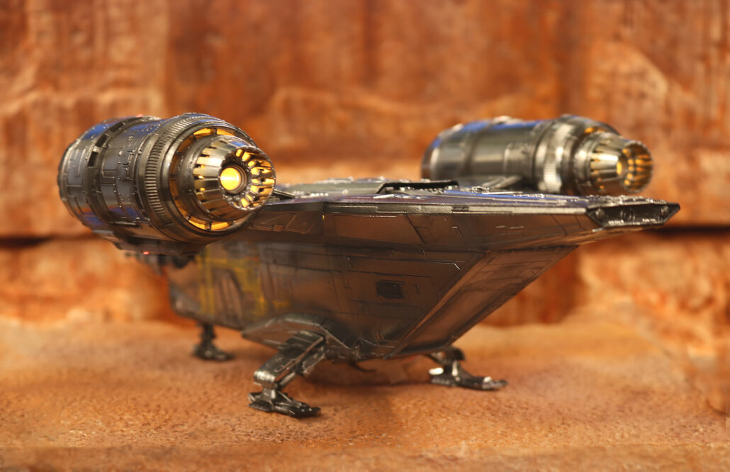
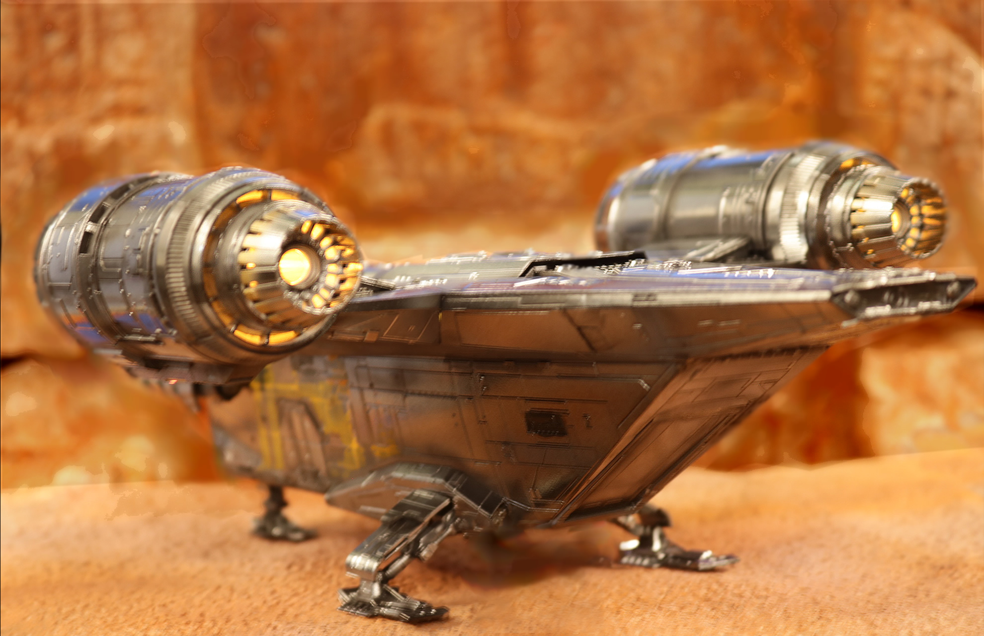
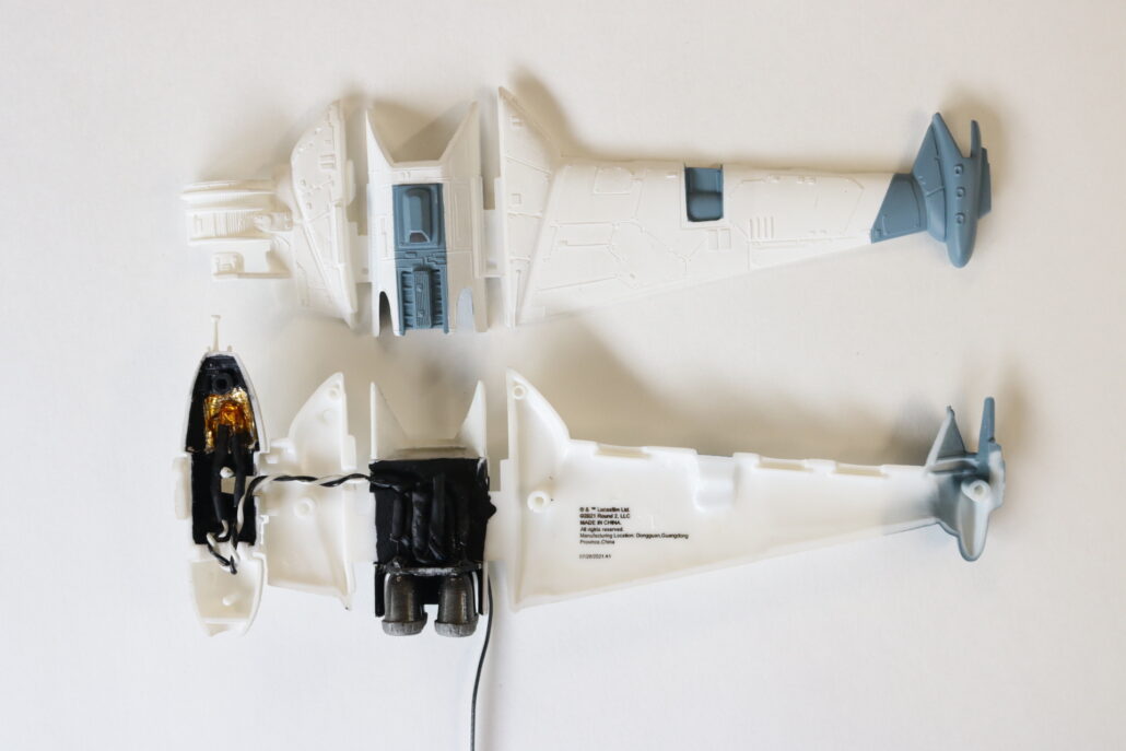
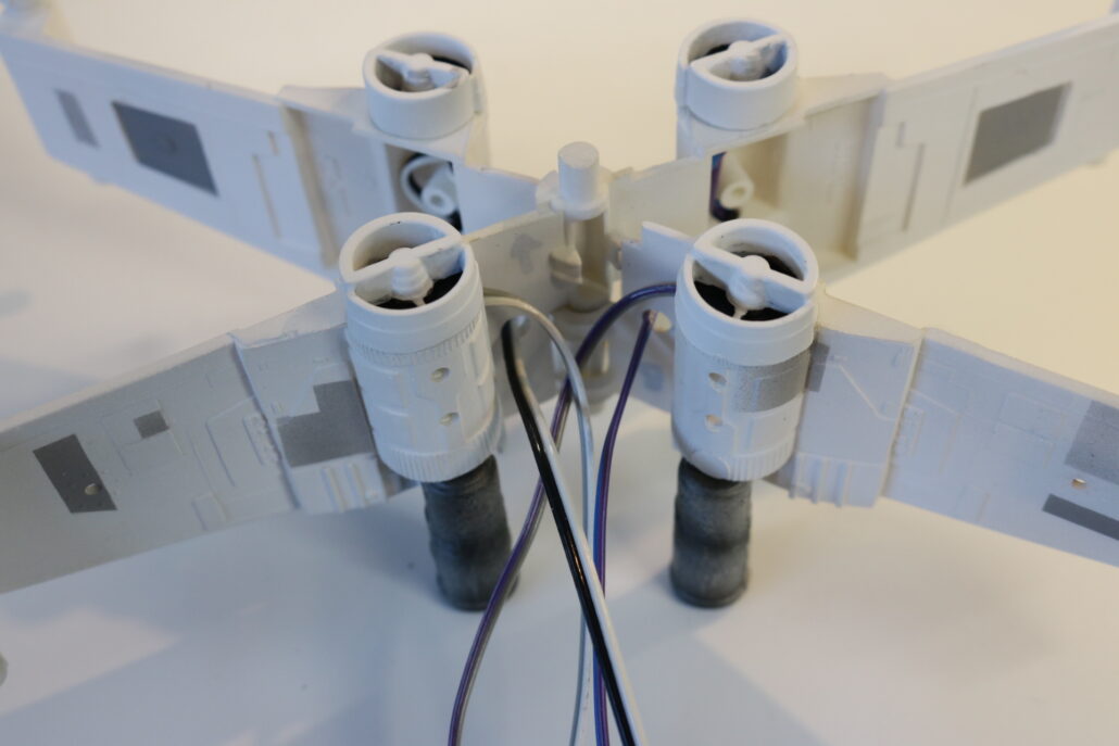
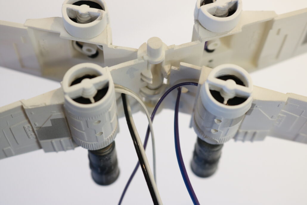
Pre Preparing The Engines:
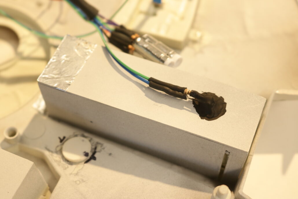
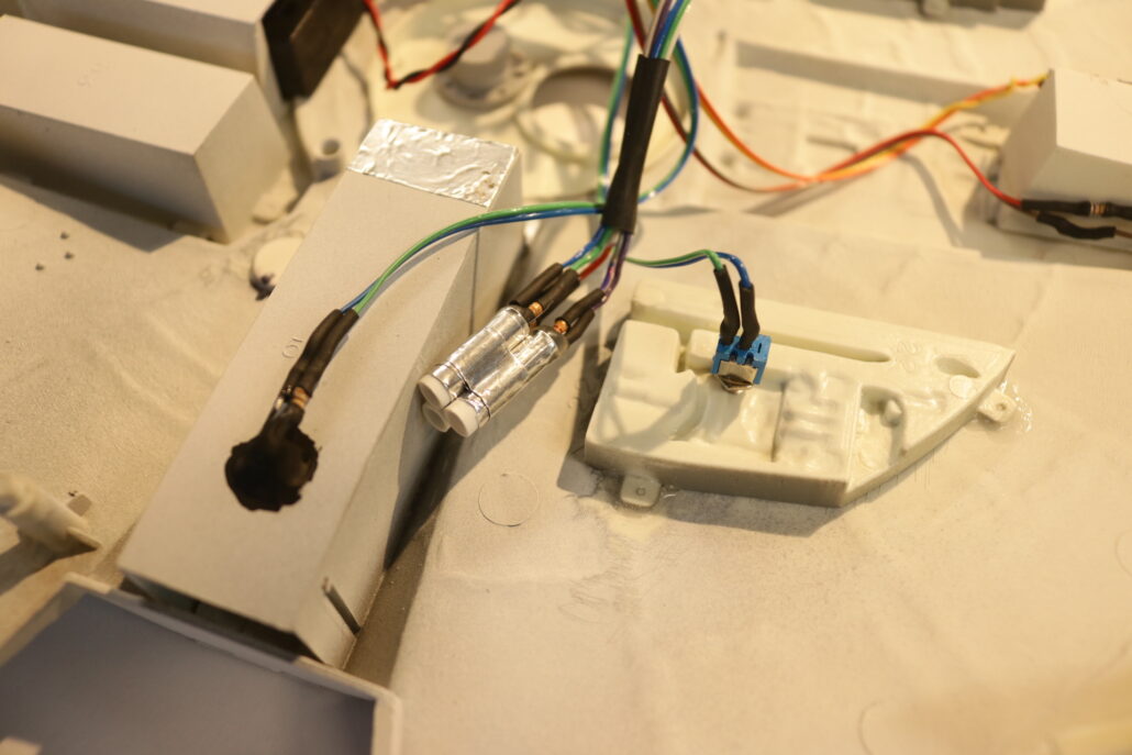
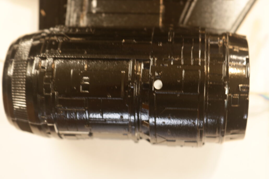
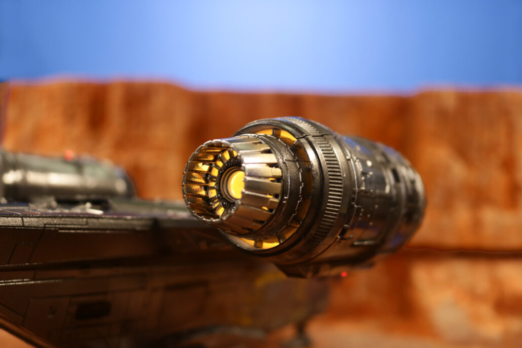
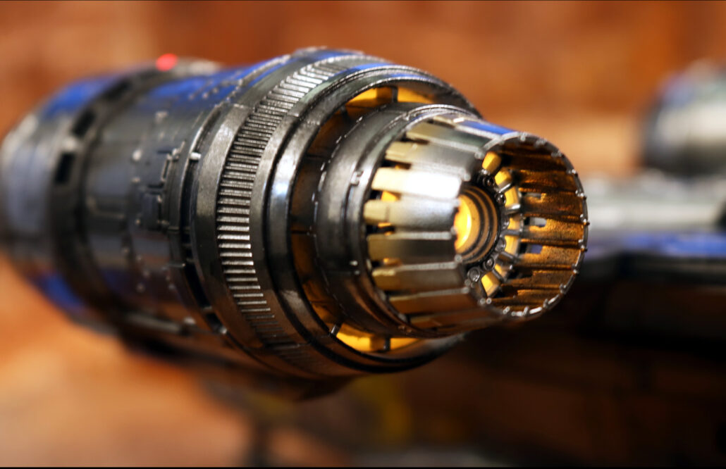
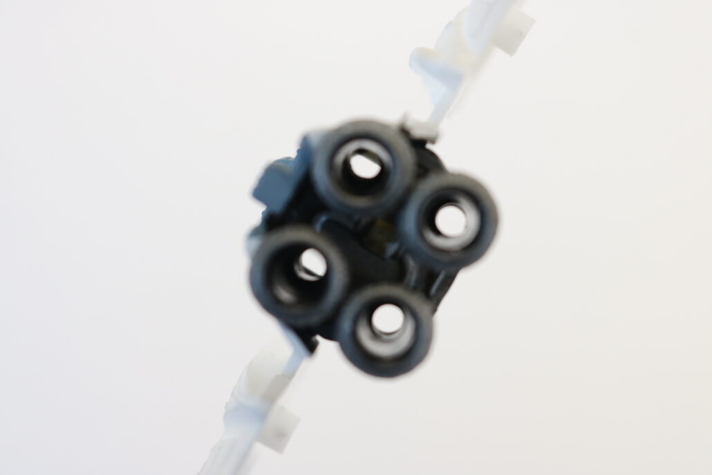
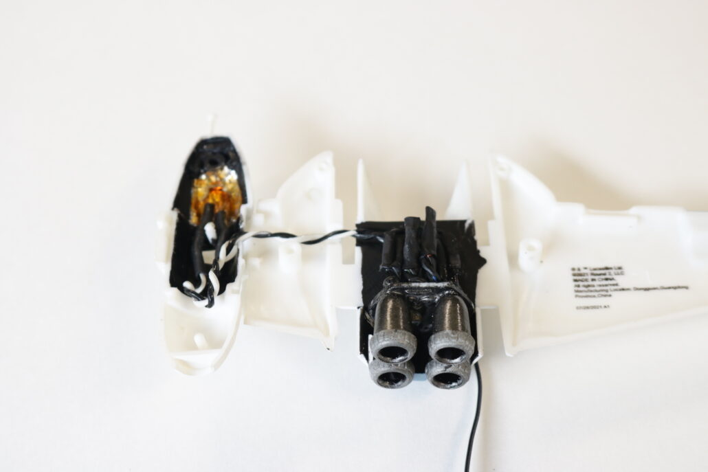
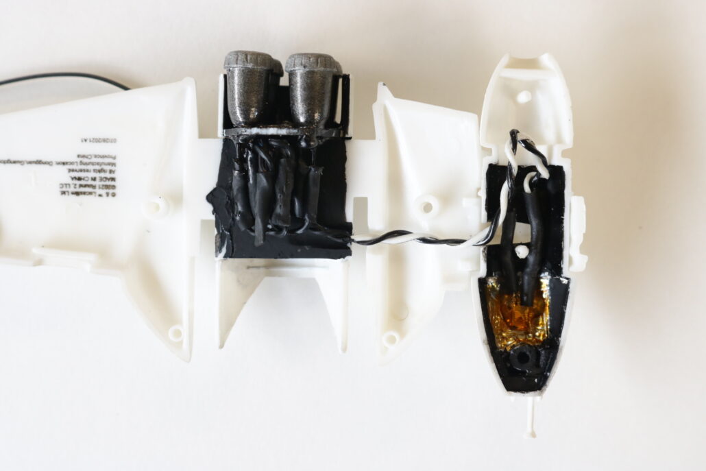
There are a few areas that will need to be monfied for the lighting. First of all I found it best to pre assemble & paint the entire engine pod prior to drill out. Drill out the 4 engines with a 3MM drill bit from the inside of the engine block. You will want to go through both the engine bell & engine block plate. Keep in mind to make all you resistor & wire connections a compact as possible since the area fill us up fast with wire & lights.
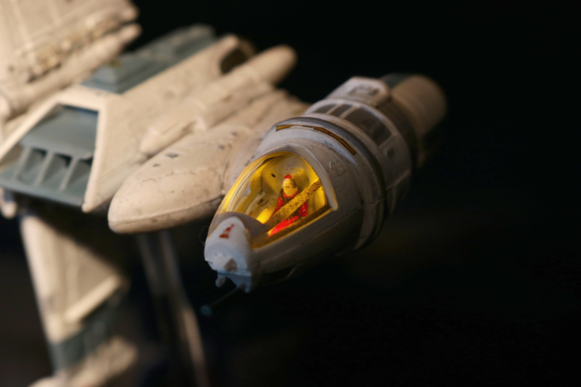
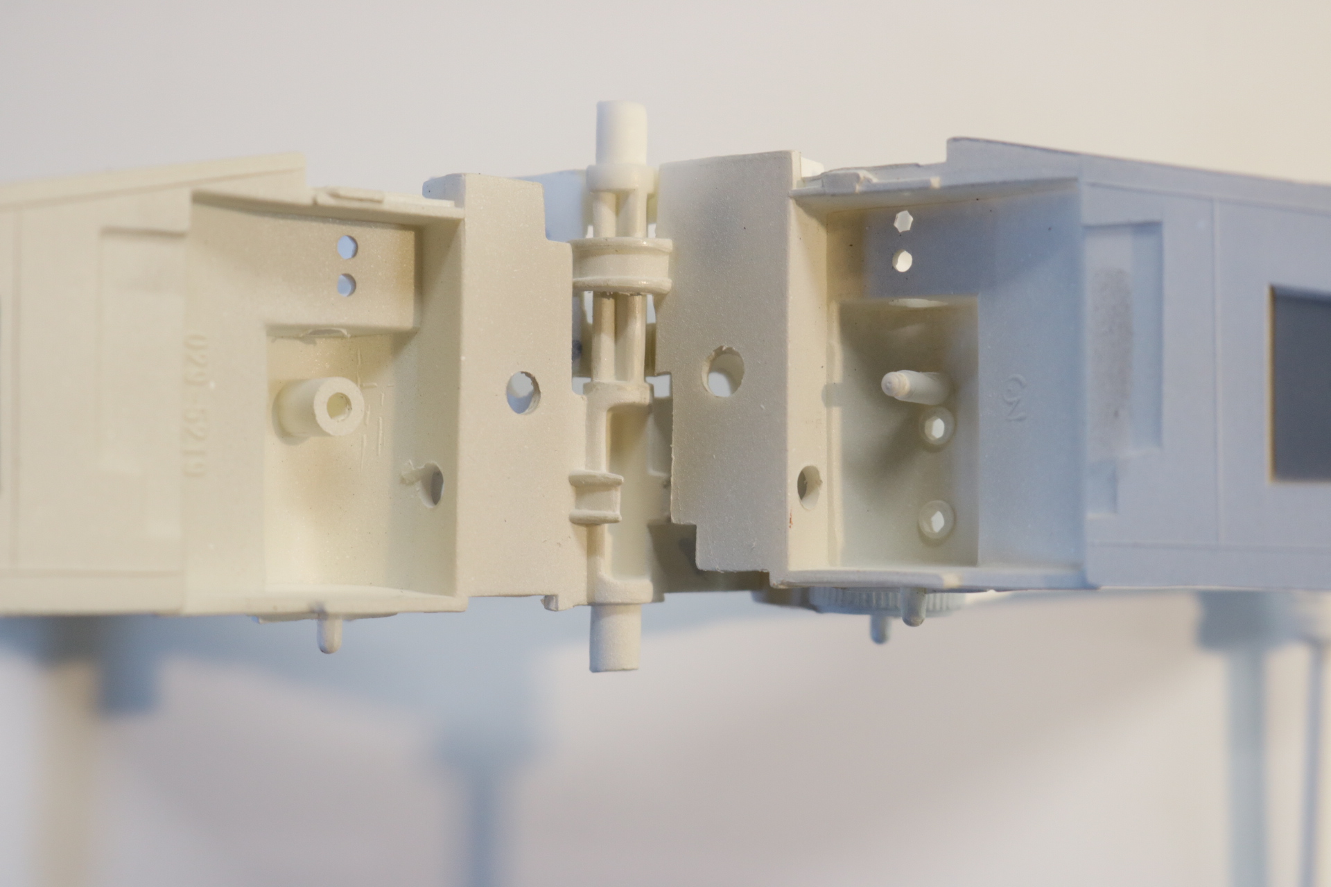
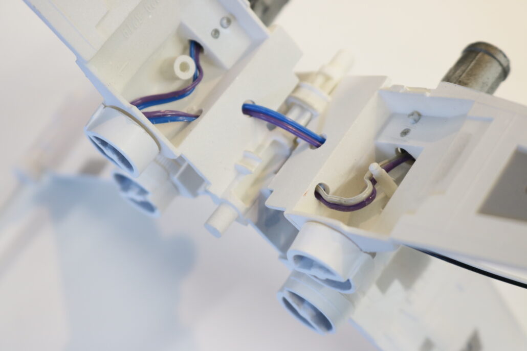
Preparing The Cockpit Area:
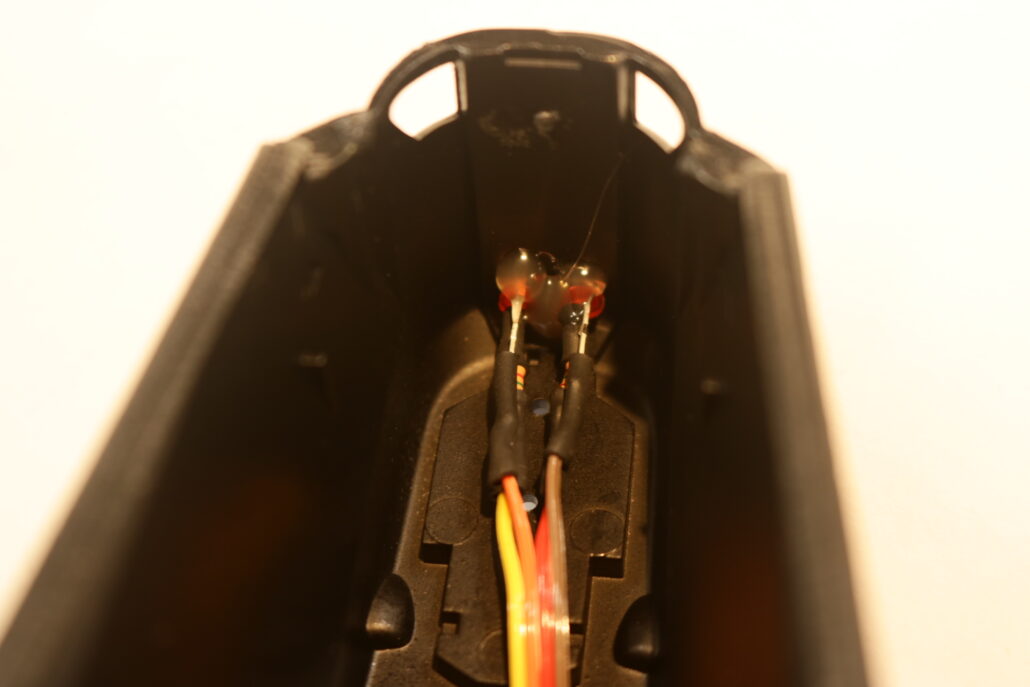
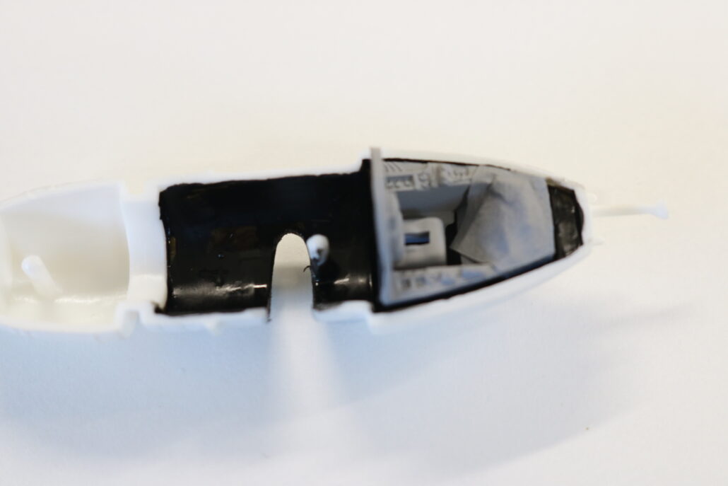
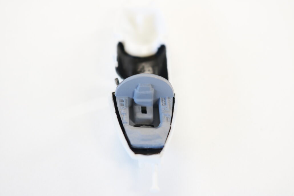
The cockpit area will need some custom channeling for the one wire to the cockpit. Since the cockpit moves you will need to cut a notch around the mid section of the cockpit tube to get rotation with out pinching off the wire connection. It is best to run a loop of wire for the cockpit towards the back and then go forward to the front of cockpit, this allows slack in the wire when the cockpit is rotated. You will need to also drill a hole through the upper gas chamber “looks like two rockets together”. The square led provided in the kit sits flat on the floor between the seat & dash board. You will need to tape & or black out areas around the led to create a dim or soft lighting effect. Test led for placement & operation before installing.
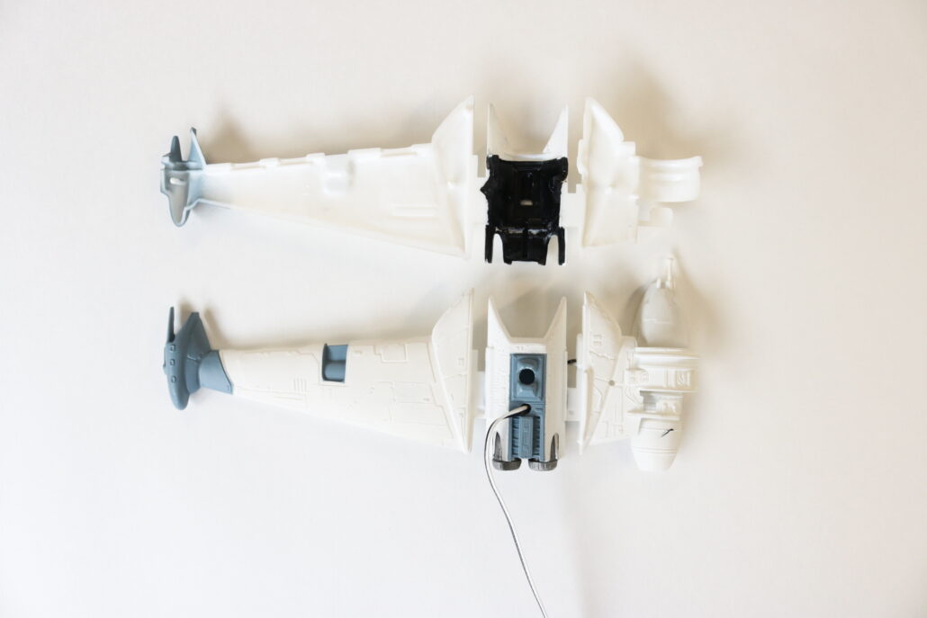
Wire Management Pre Close Up:
After pre fabricating & testing all your lighting zones for proper fit & operation your ready to start closing up the main body parts. Pay extra attention to all the wires & any areas where the wires may be come pinched. Take your time when closing up all the main sections. If you have any questions please contact us direct at randy@voodoofx.com.
First start by getting yourself familiar with all the model kit parts & where they are positioned to assemble the model. Second read all the information regarding the model lighting kit & wiring diagram. There are only a few modifications that will need to be made for the lighting system.
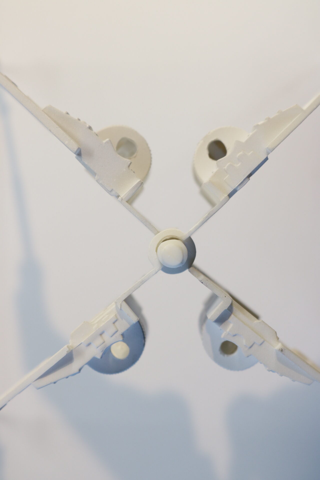
Preparing The Engine & Wing Parts:
There are only a few areas that will need to be monfied for the lighting. The fist area is the engine pods, you will need to drill out the main engine drum & remove the locating pins in the rear where the meet the engine pod. In the wings you will need to also drill out for the passage of the wiring.
Preparing Cockpit Area:
The cockpit area will need to be taped off on both sides of the dash board, this will allow the lighting to pass through the part and light the dash board. I is also a good idea to black out the areas in the cockpit both upper & lower to avoid light leek & shine through.
Preparing Clear Replacement Engine Cowls:
The replacement clear parts for the deluxe kit will need some prep before install. Its best to use a small amount of liquid latex on the inside area & the back side of clear parts to maximize the lighting effect. After the latex has fully dried you can apply thin layers of paint to block any light from shinning through the cowl. Your now ready to pull the latex out of the inside & back of the cowl exposing the clear inside & back. Carefully hand paint the inside of the fan blades, you may need a few coats to properly cover the raised areas.
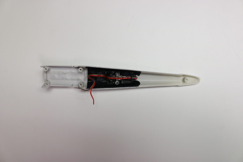
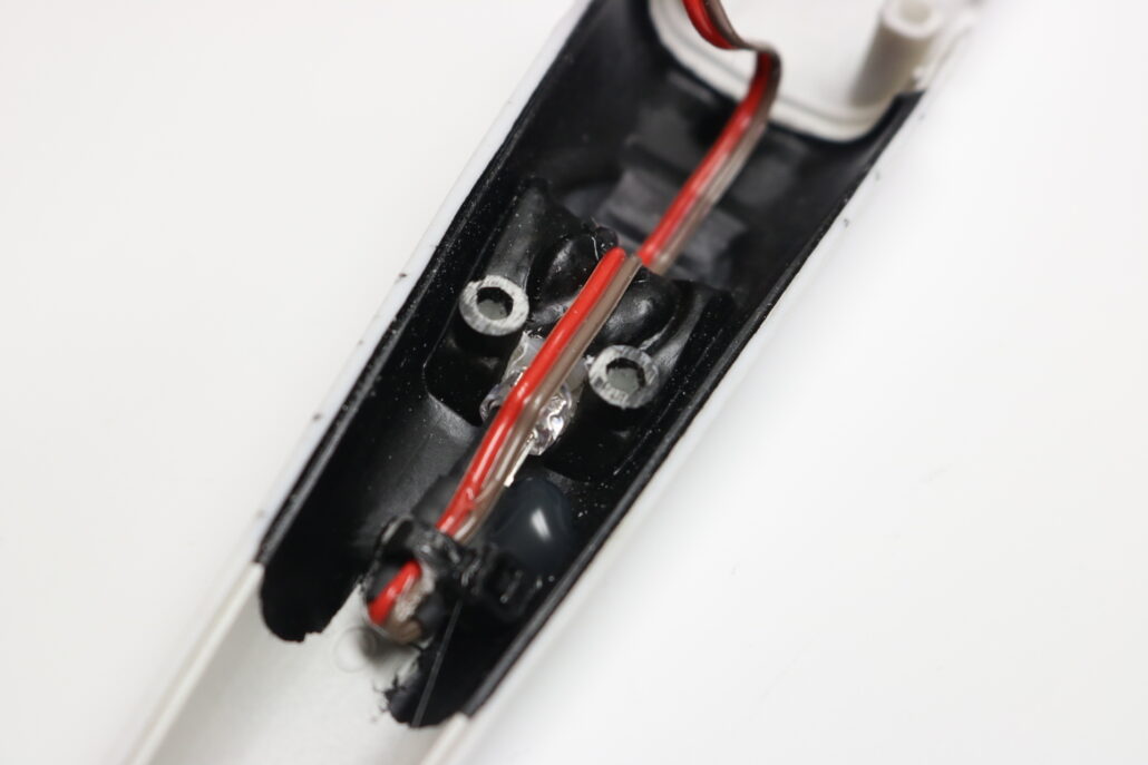
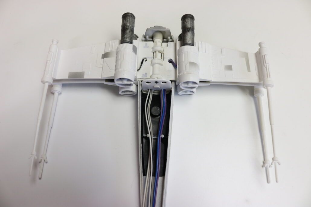
Pre Wiring The Engine & Install On Wing:
It is best to pre wire & pre pint the engine pods at this stage. Once you have all the pods wired you are ready to install & test the lighting one at a time. The best way is to loosely fit the wings together and run all the wiring forward into the main part of the fuselage, you will need to drill out some ports in the forward wing mount brace. Make sure to fallow the wiring diagram for reference, each led used in this lighting package will require a in line resistor for each led used. Its best to build in each resistor into the engine pod & make the runs for the finial hook up since you run out of room fast.
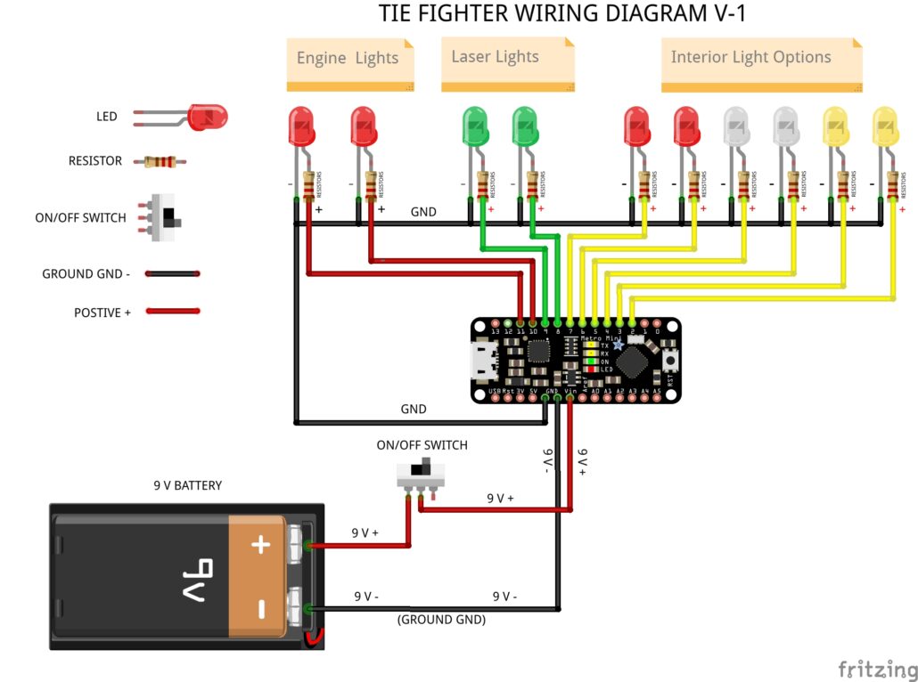
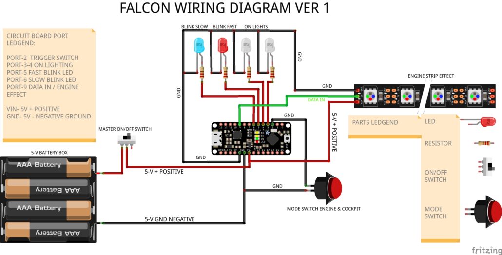
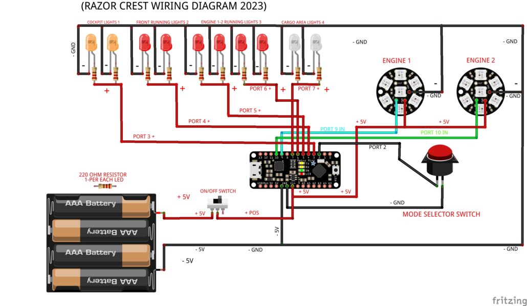
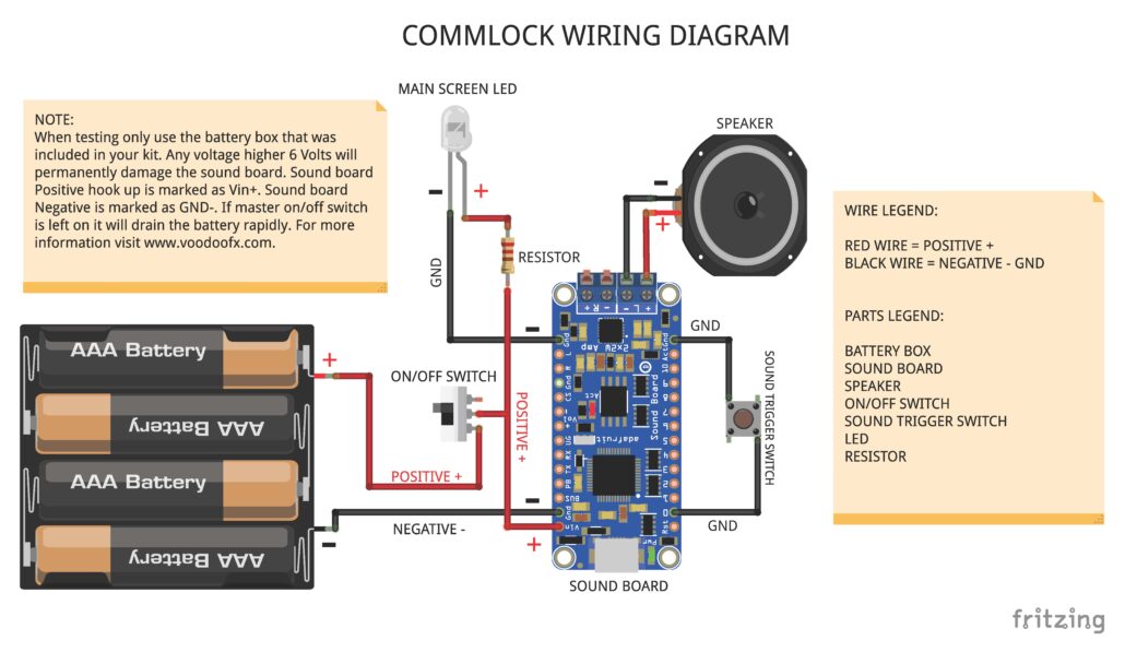
Wiring Diagram:
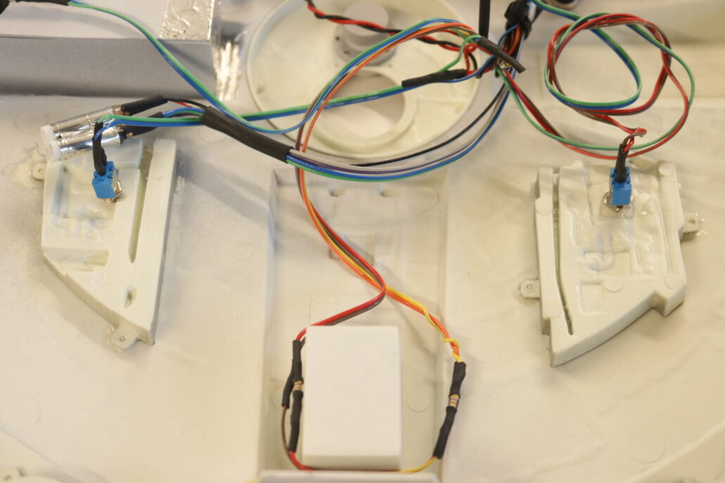
Here is how to wire the lighting for the model. Its best to have all the wiring & resistors to all self contained with in the model & run one set of positive & negative wires out the bottom of the hull & put your battery, on/off switch in a base box, this will need to be scratch built to your speck.
First start by getting yourself familiar with all the model kit parts & where they are positioned to assemble the model. Second read all the information regarding the model lighting kit & wiring diagram. There are only a few modifications that will need to be made for the lighting system.
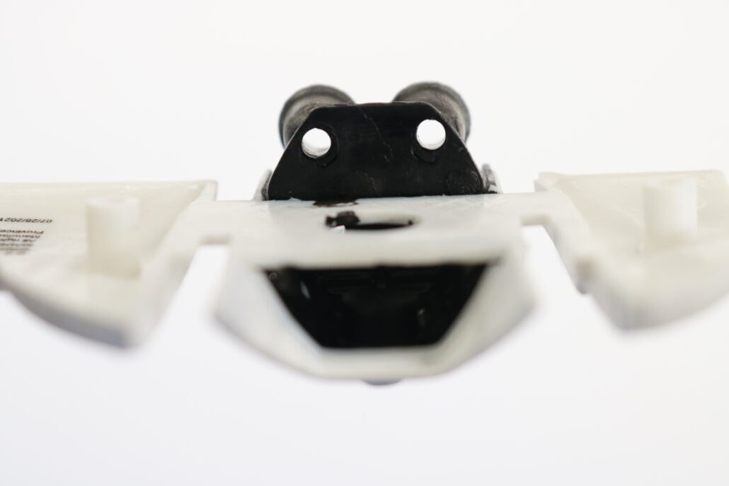
Preparing The Parts:
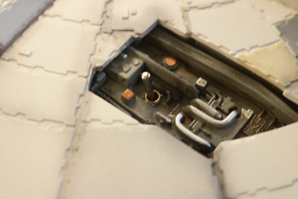
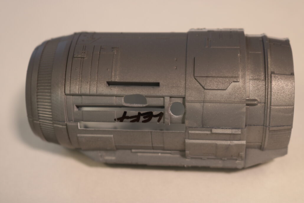
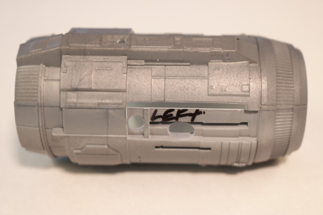
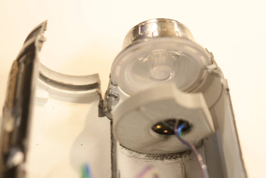
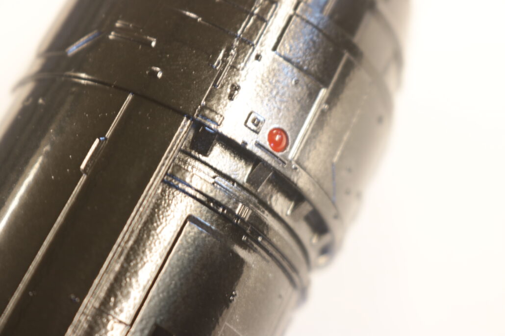
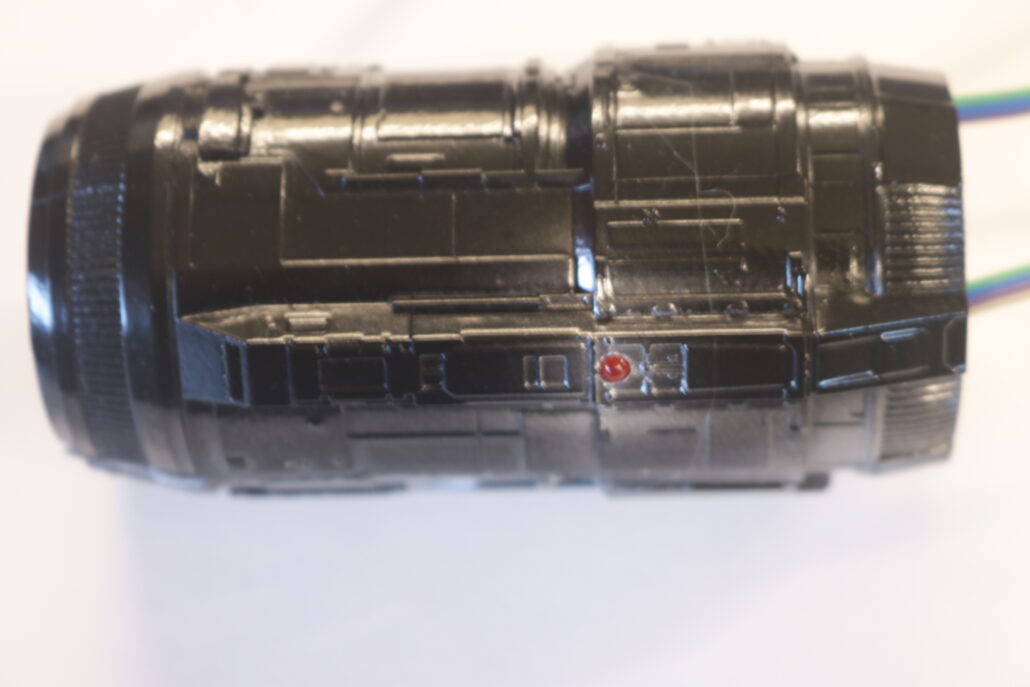
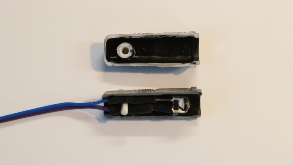
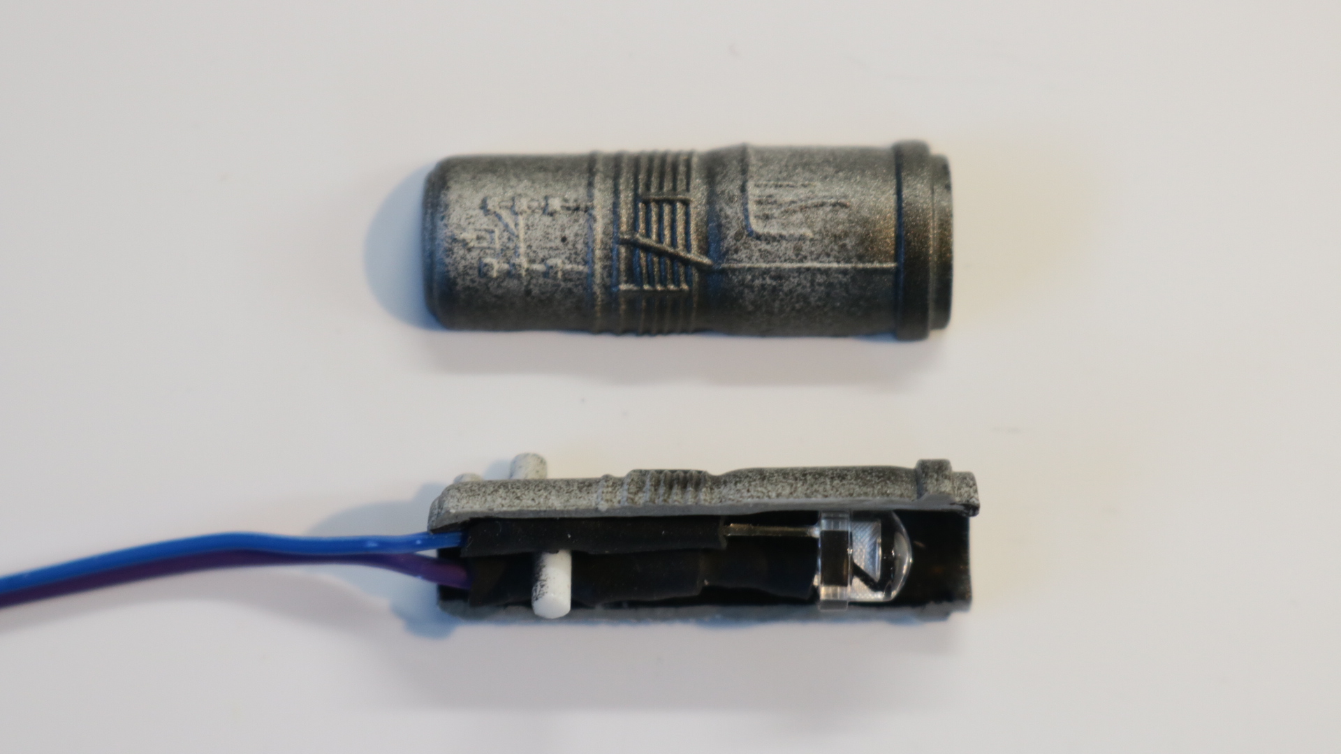
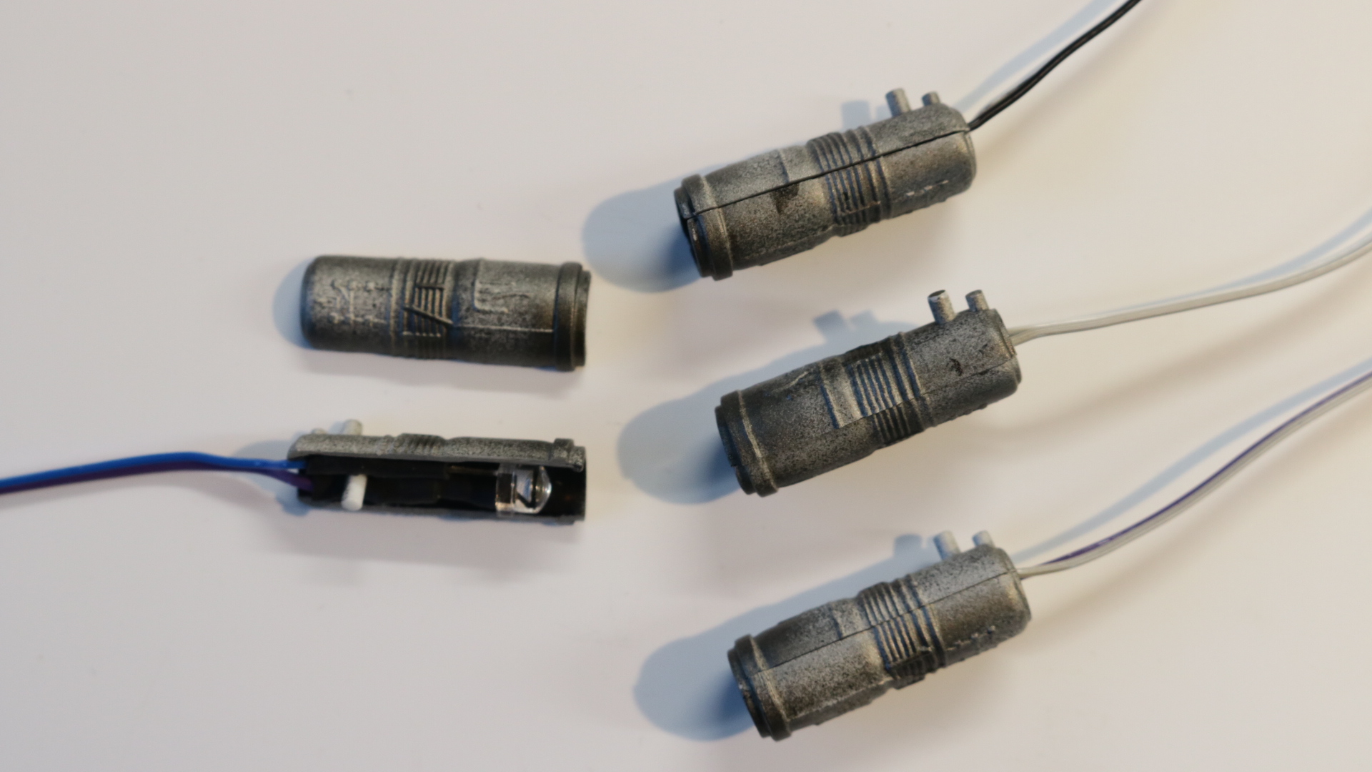
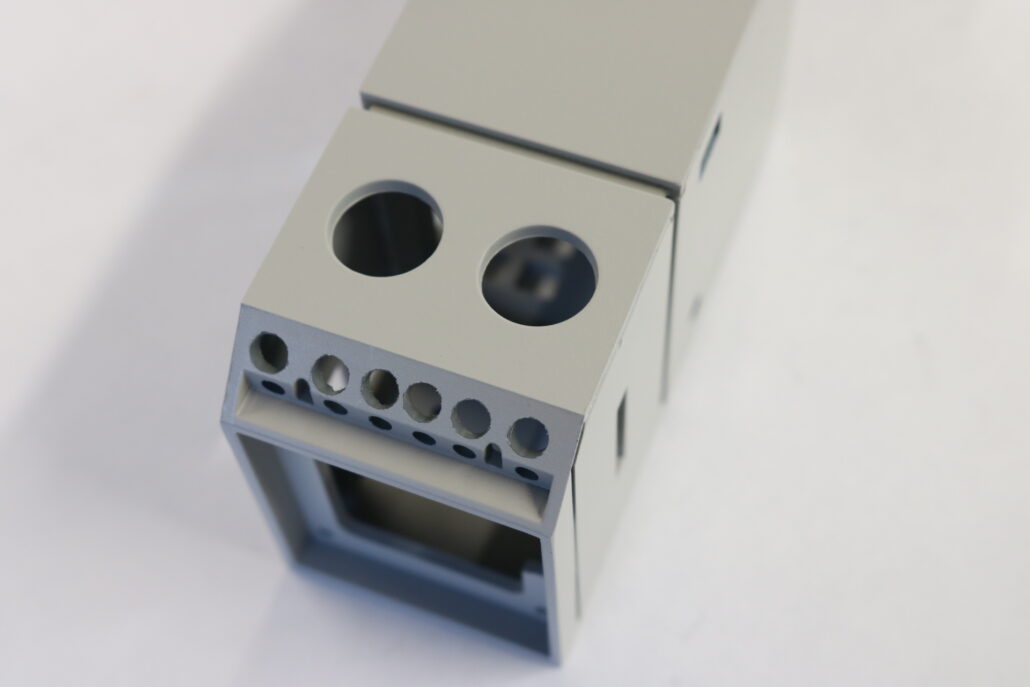
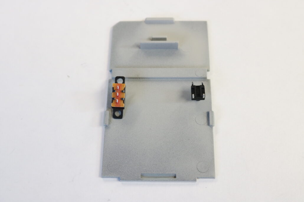
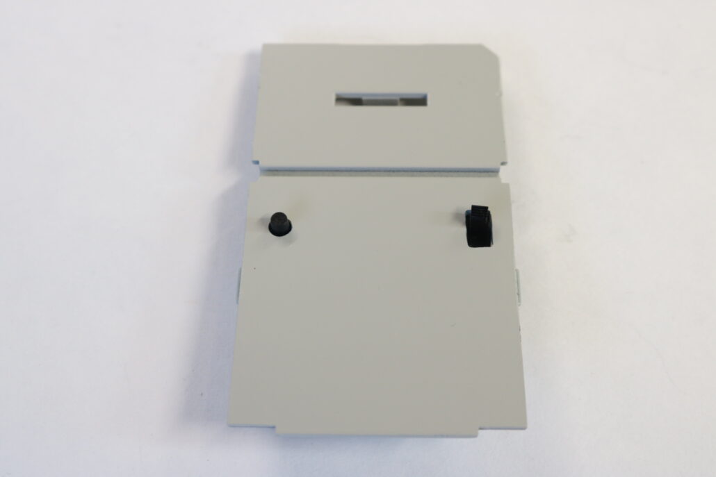
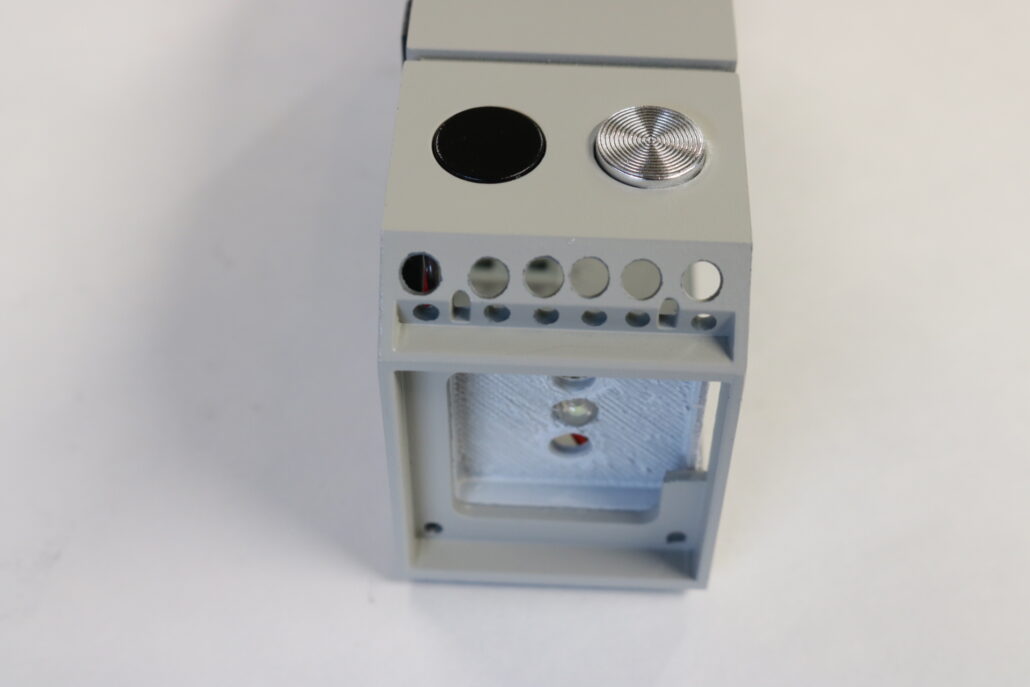
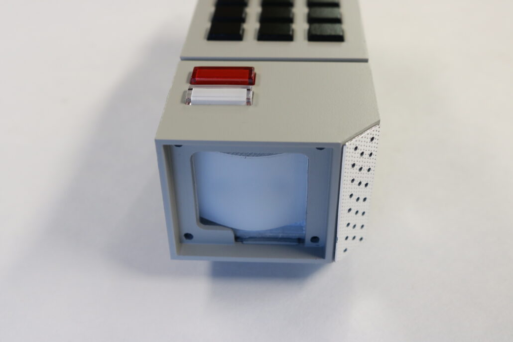
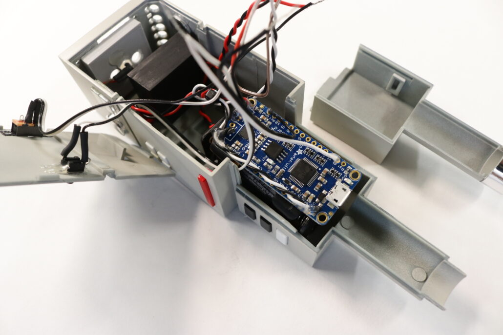
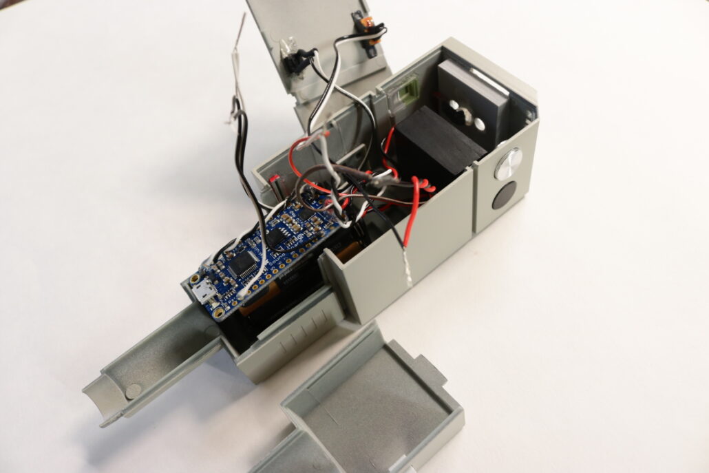
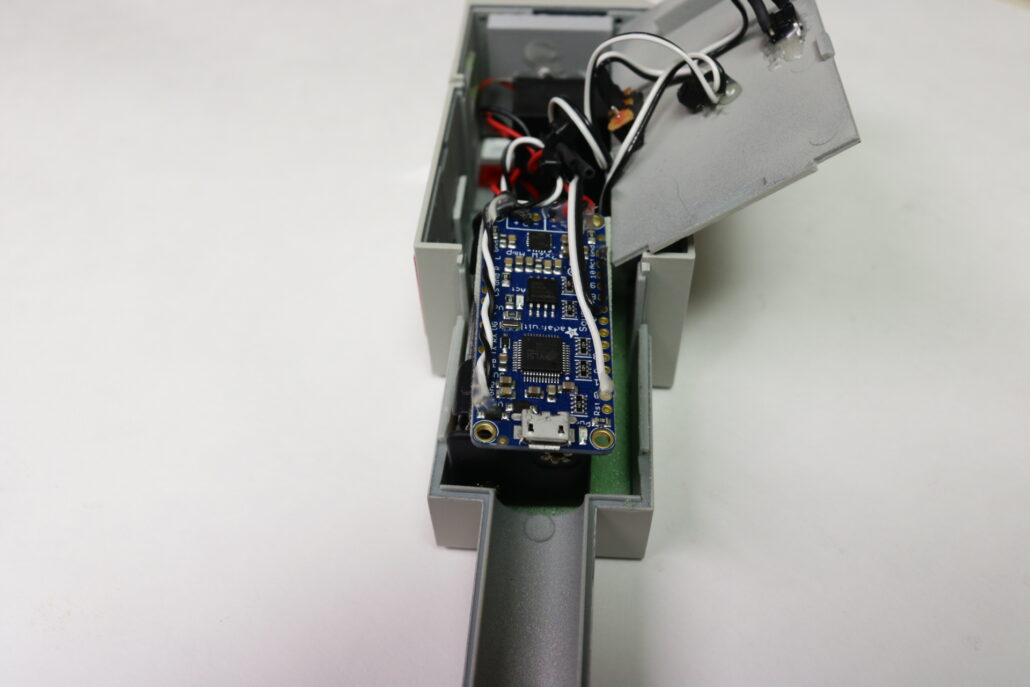
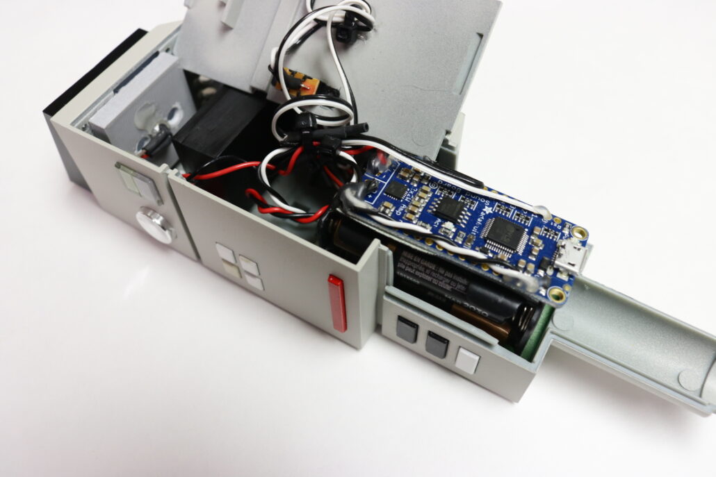
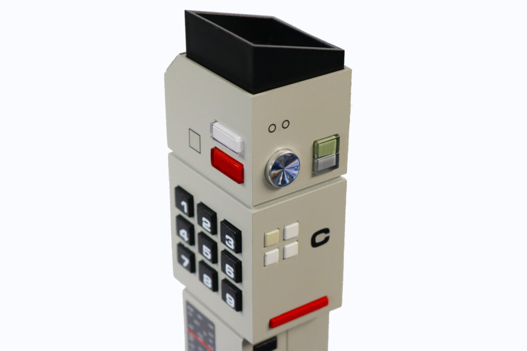
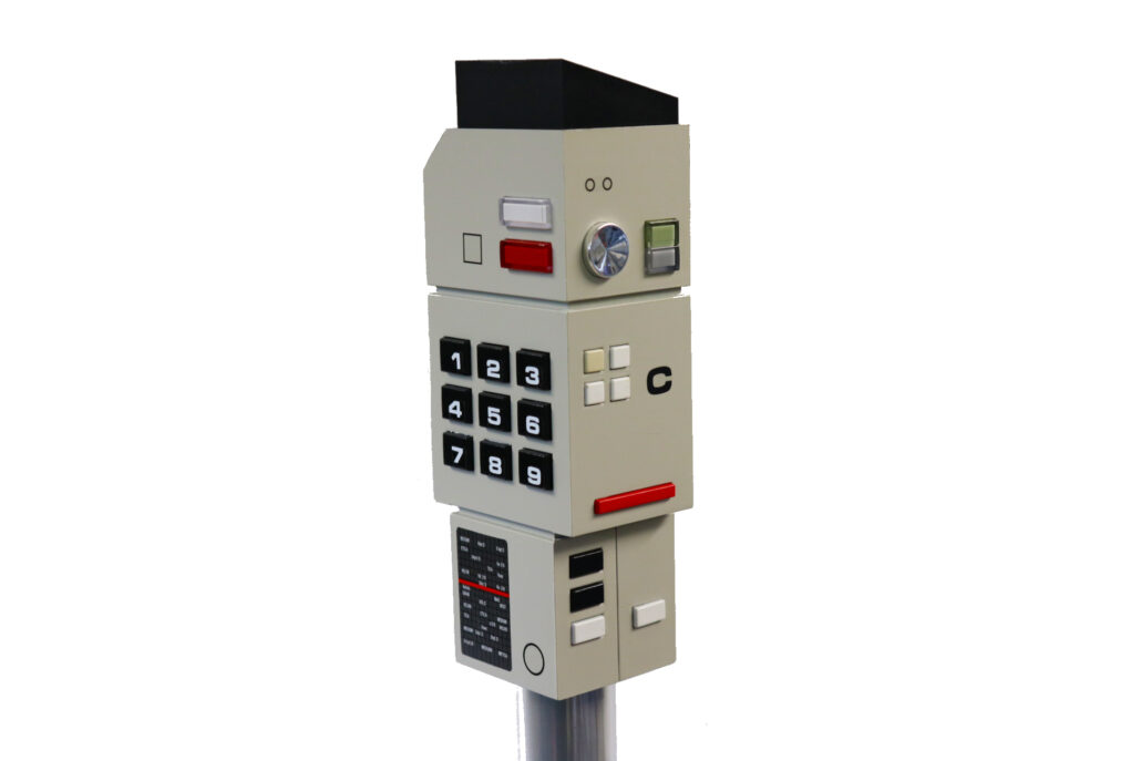
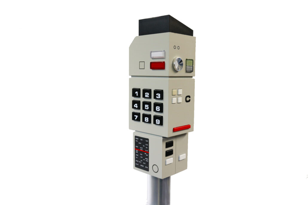
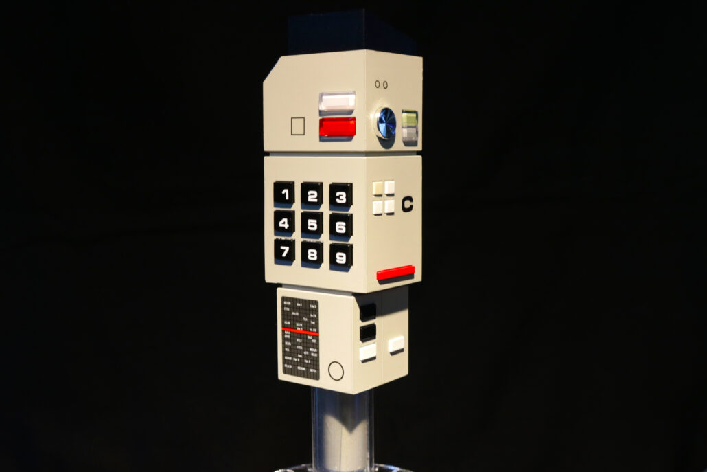
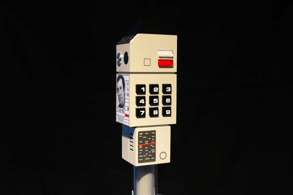
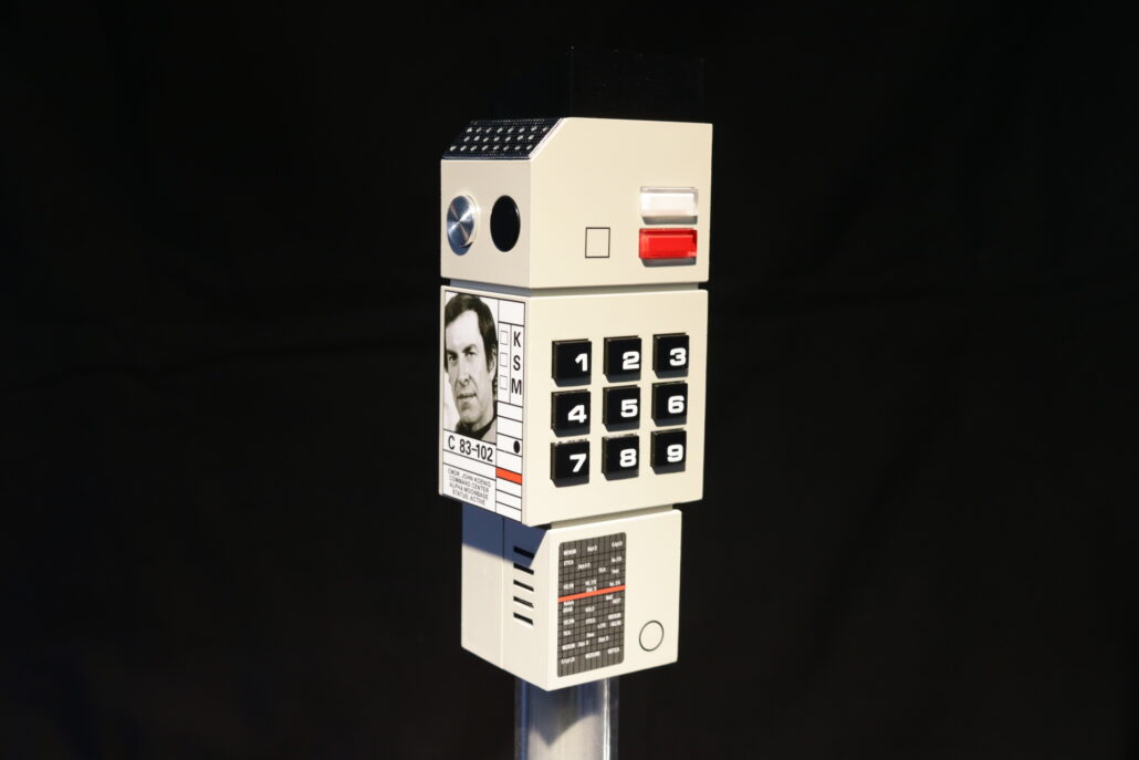
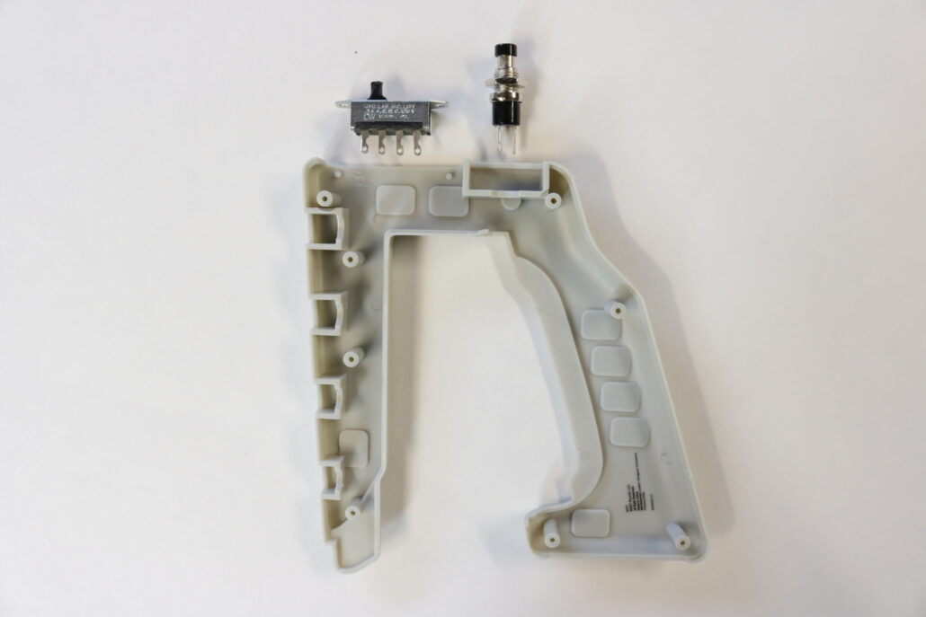
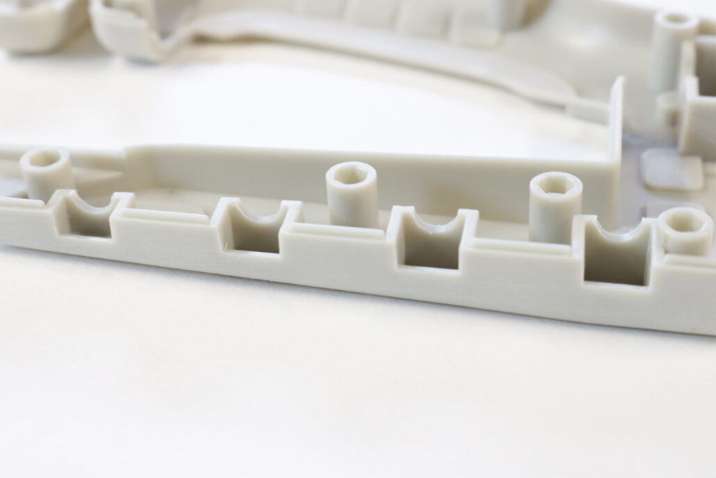
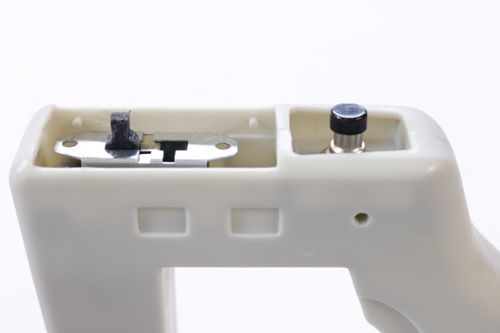
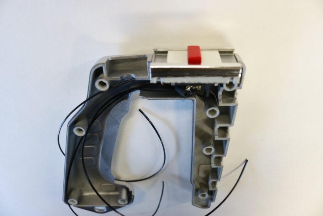
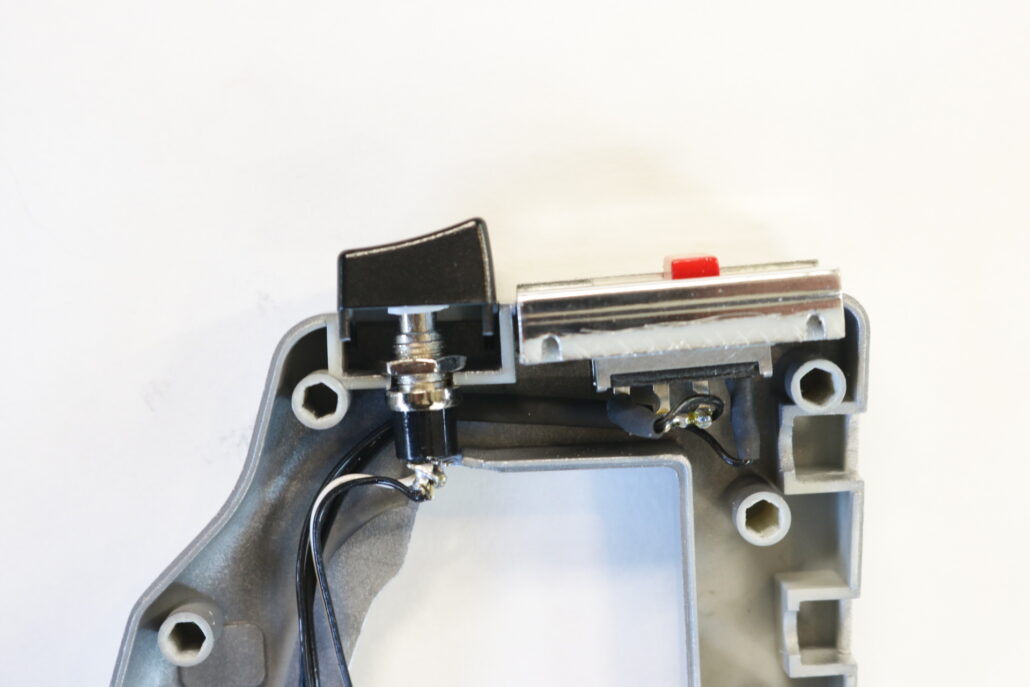
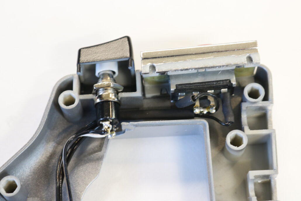
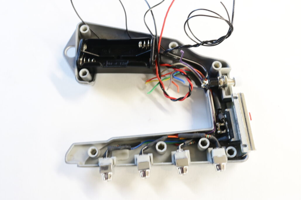
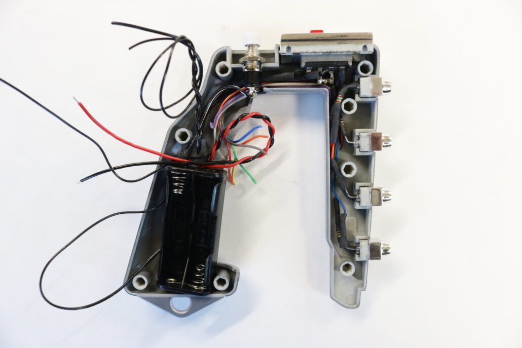
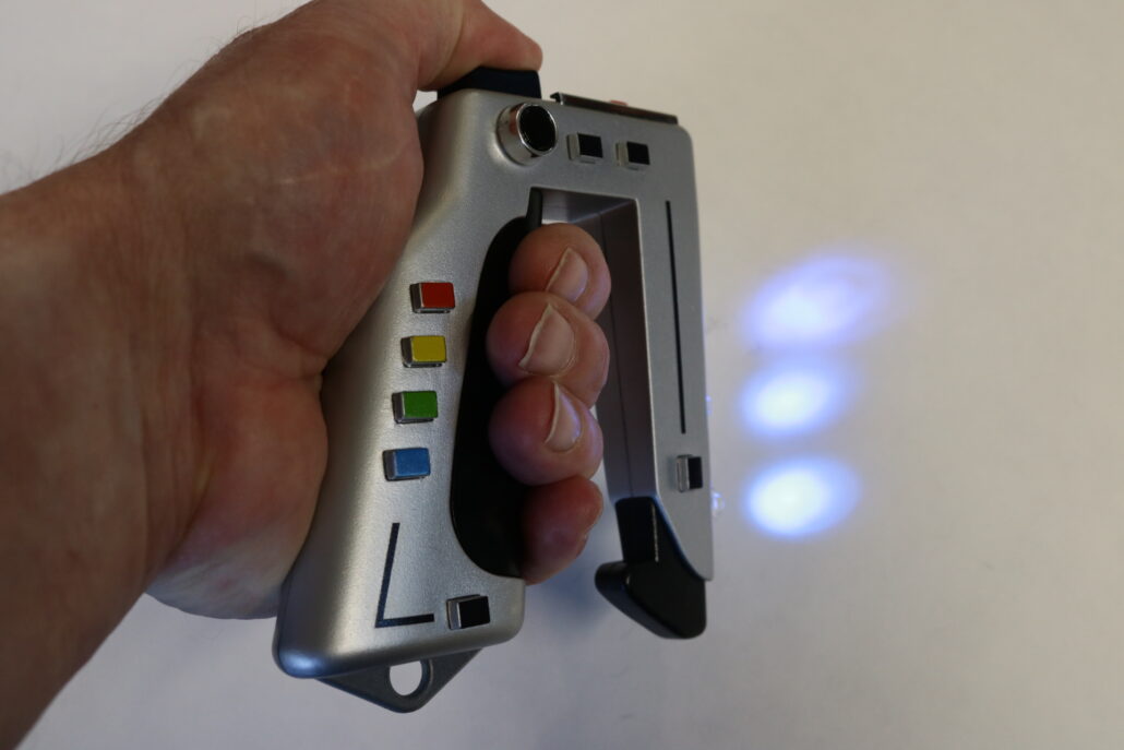
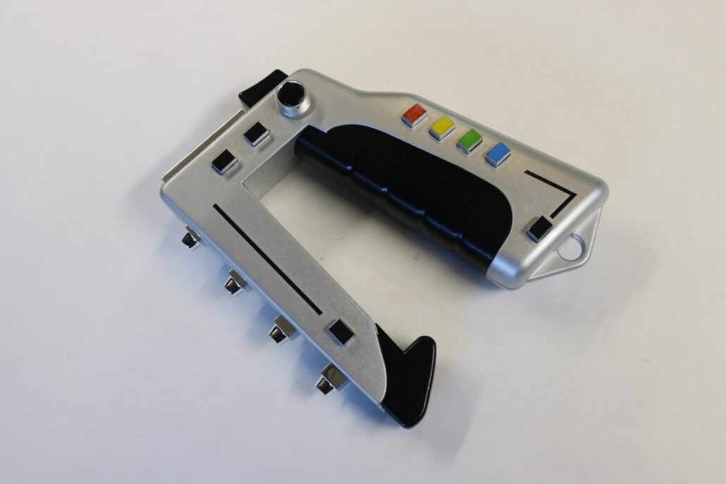
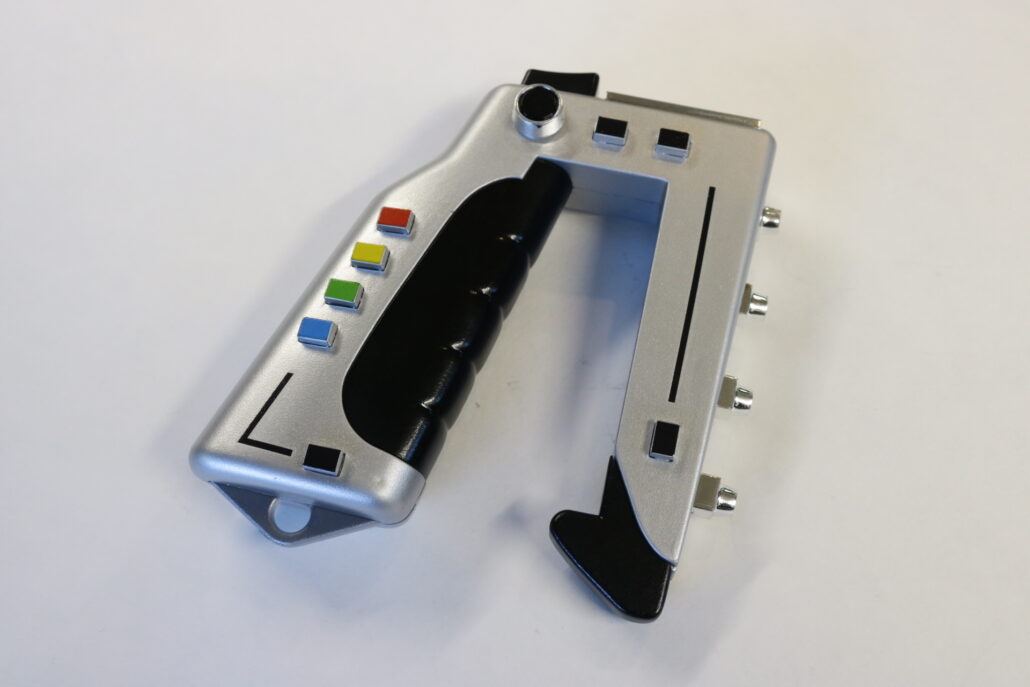
There are only a few areas that will need to be modified. One of the areas that will need to be drilled out is the speaker grill & the commlock body under neath the grill. You will need to make a series of holes to let the sound through the speaker grill & body. Another area is the back side of the belt clip, in this build I used the backside to the hide the on/off switch & momentary trigger for the sounds. You may decide that you want to use the keypad or other buttons to active these two main functions, additional switches will need to be purchased separately.
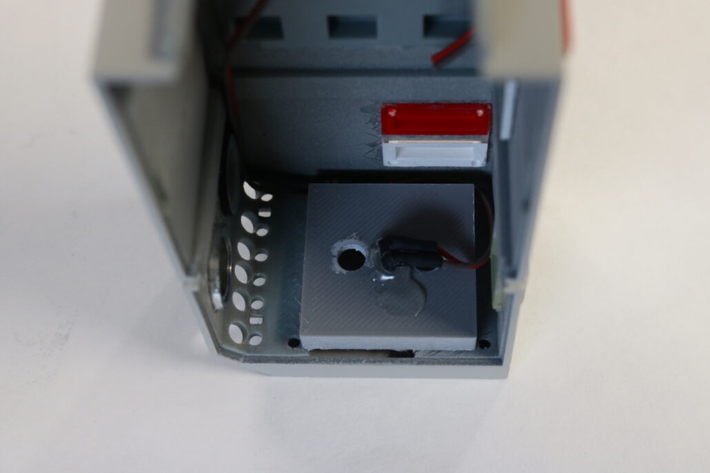
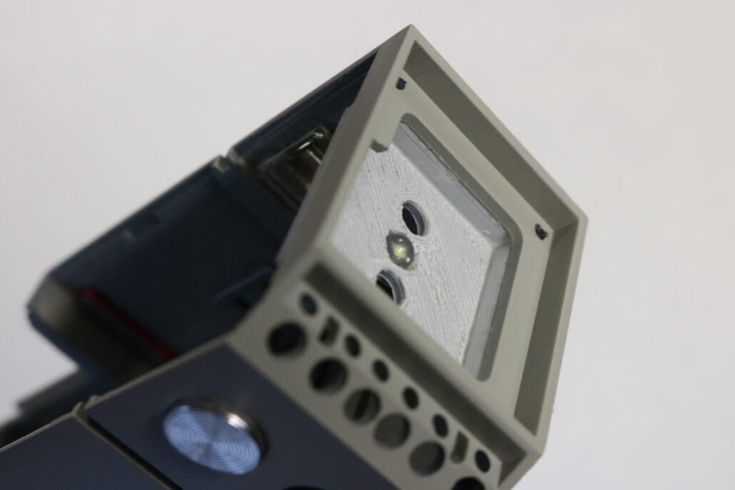
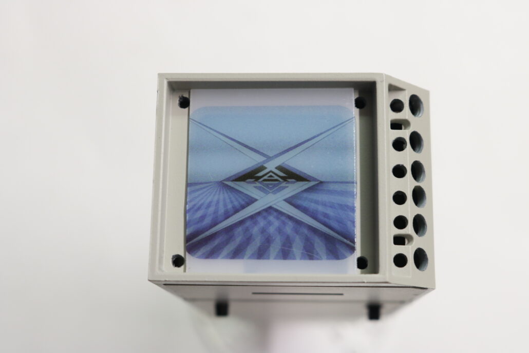
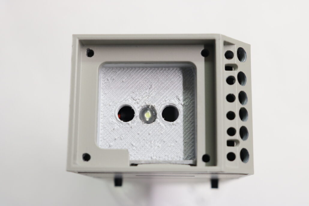
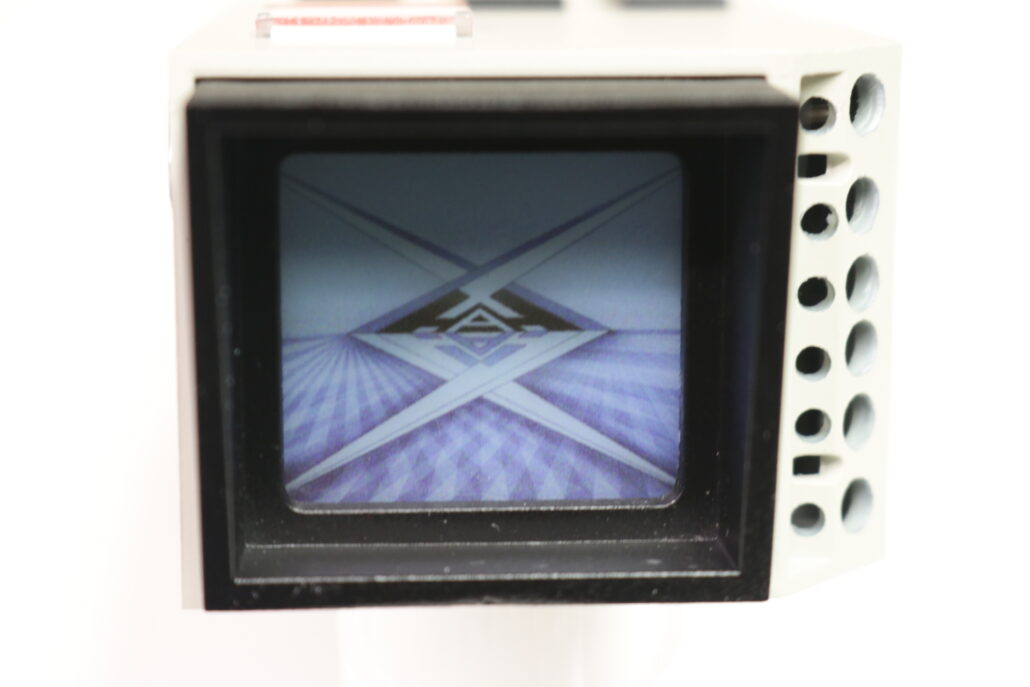
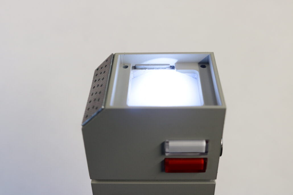
Preparing Led & Light Box:
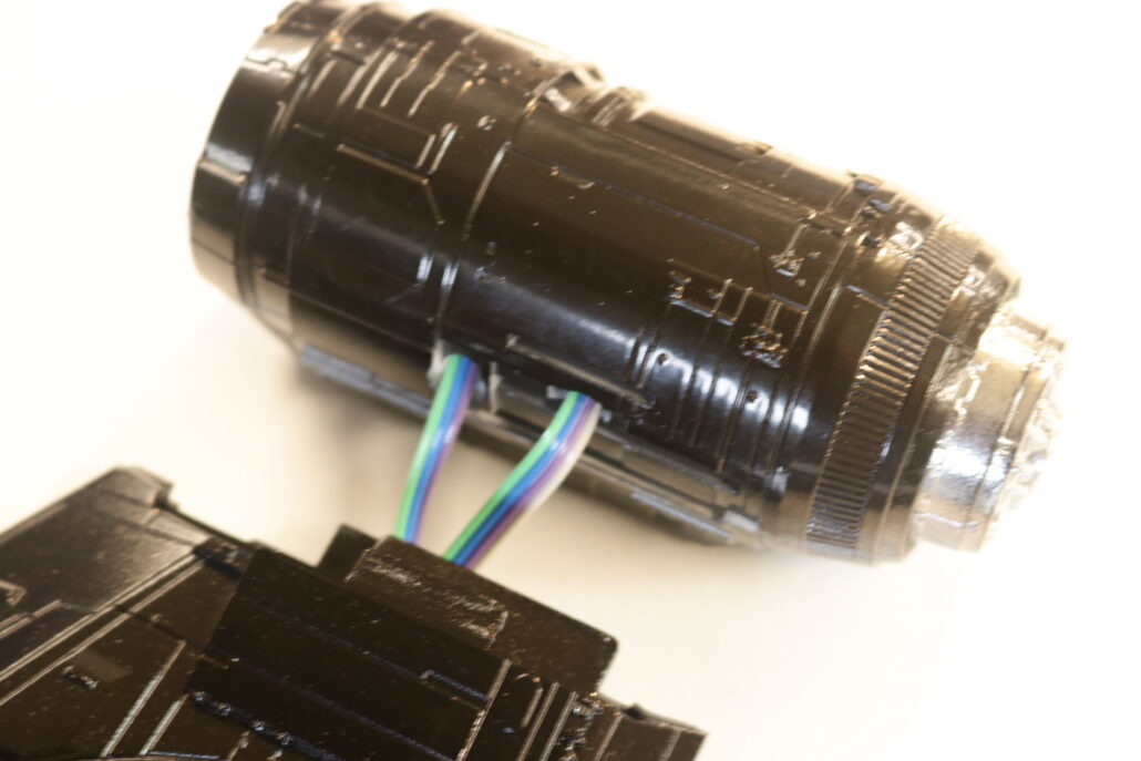
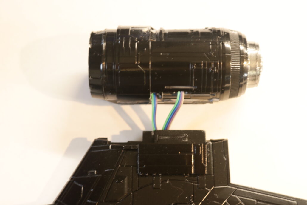
Since their is only one led for the main viewing screen it is best to prefabricate the led with a single in line resistor for this application. The view screen led is tied direct to the on & off power switch & only comes on when the main power is turned on. The light box files are provided as a free download STL file for 3D printing but if you do not have a printer you will need to scratch build a shallow light box to support the one led for the view screen. The view screen will also require a small piece of diffusion material cut out for both the light box & the decal being used. The light box diffusion can be slightly bent causing a curve but not going over the main body part. If you dont have the after market translite decal from Yaymonsters.com than you will need to cut to fit the diffusion material to fit the screen space & mount the stock decal on to the diffusion material.
Fitting Of Parts:
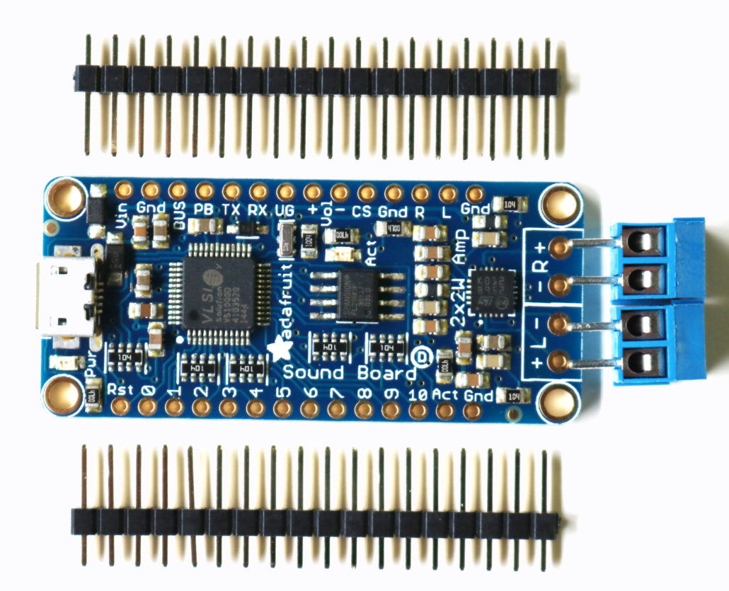
Sound Board & Trigger:
The sound board is based on a “5V Only” power set up, so it is important to only power this unit with 5 volts, any power greater that 5 volts will permanently damage the sound board. The sound player can be set up in 5 different modes or functions. All the sound features are triggered by a momentary switch tied to a corresponding port number on the circuit board. One side if the trigger switch is tied to the port selected and the other side goes to ground or GND port. Its all on how the sound files are set up to play. Down below is the basic trigger function brake down.
This page will talk only about using it in trigger mode since that’s what we think most people will do.
How Many Triggers Are There:
There are eleven trigger pins – named #0 thru #10
You don’t have to use them all! We just had lots of pins so we made them all available.
Each trigger pin is an input that we recommend using with a pushbutton or tactile button or other kind of switch. When the # pin is connected to GND for more than about 125 milliseconds it will trigger! There is a 100K pull up resistor on each one, so you do not need any extra resistors or pullups.
Remember, you don’t have to use a mechanical button or switch – you can use conductive thread, tilt switches, two pieces of tinfoil, the output from some other electronic thingy, just anything that will send a ground signal to the pin.
How Long Does It Take For Audio To Play Once I’ve Triggered The Pin:
Good question! It matters whether you are using WAV or OGG. Compressed audio takes a little more time to get going.
From the moment the SFX board sees a ground level on the pin, it takes ~120ms to play a WAV file and ~200ms to play an OGG file.
If ‘repeating’ a file by keeping the button hend down, or doing a latching trigger type, theres a ~20ms delay (imperceptable) between WAV replays and ~120ms between OGG replays (noticable if the audio is meant to perfectly loop)
Trigger Types:
There’s a lot of different ways you may want to play your sound effects. Normally a microcontroller would be required to get exactly what you want, but the Sound Board is pretty smart and has the ability to play audio a couple different ways depending on the file name
There’s no code or firmware involved, only the file name of the audio file!
Let’s understand this by going through the five types:
Basic Trigger – Tnn.WAV or Tnn.OGG
The first type is the ‘basic trigger’ – when the button is pressed, audio plays. The entire file is played from beginning to end once.
To enable this trigger, name the file Tnn.WAV or Tnn.OGG where nn is the trigger #. For example, if you want to use pin #0, the file could be called T00.WAV (that’s two zeros after the T), if you want to use pin #6, T06.OGG – all the way up to T11.WAV
Hold Looping Trigger – TnnHOLDL.WAV or TnnHOLDL.OGG
This is a more complex trigger. Instead of pressing once the button to play, it plays ONLY when the button is held down. Great for “hold the button down to play the ray gun blaster sound effect” Call the file T02HOLDL.WAV for example
As long as the trigger pin is connected to ground, it will continue to play the same track on repeat. If you want a perfectly smooth transition between the end and beginning, we suggest WAV files, as OGG decompression takes a few milliseconds and has a noticable delay.
Latching Loop Trigger – TnnLATCH.WAV or TnnLATCH.OGG
This is a little like the Hold Looping trigger but you do not need to keep the button held down. Instead, press the button once to start the looping effect, then press it again to stop.
This is maybe good for if you want a continuous effect without having to keep the pin held down. Call the audio file T08LATCH.OGG for example
If you want a perfectly smooth transition between the end and beginning, we suggest WAV files, as OGG decompression takes a few milliseconds and has a noticable delay.
Play Next Trigger – TnnNEXT#.WAV or TnnNEXT#.OGG
Lets say you want to have one button but many different sound effects. For example, a stuffed animal that has a squeeze sensor trigger. It would say different things each time it is squeezed. For this kind of effect, use the Play Next Trigger.
This trigger is basically like the basic trigger, one button press per play, but you can have multiple effects on one pin
You can have up to 10 audio files triggered on one pin, they will play in order. For example, if you’re using pin #3, the files would be named T03NEXT0.WAV, T03NEXT1.WAV, T03NEXT2.OGG etc. up to T03NEXT9.WAV
Just make sure it starts with #0, and put as many as you like up to #9. You do not need to use all 10 ‘# slots’ up. If a number is missing, like T03NEXT3.WAV doesn’t exist, it will automatically play #0 again.
Play Random Trigger- TnnRAND#.WAV or TnnRAND#.OGG
OK so you like the Play Next mode but you don’t want to have it always in the same order? Use Play Random mode. You can have up to 10 audio effects, from say T07RAND0.OGG uo to T07RAND9.OGG
When the button is pressed, a ‘random’ track will be played.
Please note, this is not ‘cryptographic quality’ randomness 🙂 In fact, it will play through all of the tracks at least once (but in any order) before repeating.
Creating Your Own Audio Files:
You can easily put your own sound effects into the sound player by using the micro USB cable connector & your computer. The file shows up as a external drive devise, all you will need to do is build your own sound loops remove the ones that are on the board & copy & paste them to the drive.
Now you know it all works, you’ll need to create your own audio files. The sound board does not support MP3 so if you have your audio clips in MP3 format you’ll have to convert them to OGG or WAV
You can use either OGG or WAV format, and you can ‘mix and match’ so some files are OGG and some are WAV
There’s some pro’s and con’s to the two formats:
OGG is compressed, but still sounds great. It uses much less space so if you want to say store a full 2 or 3 minute song, you’ll need to go with this. However, it does take a few milliseconds to start playing the file, so if you want to have perfectly looping audio, OGG will have a gap in between each play through
WAV is uncompressed, so its the highest quality. But it takes up a lot of space. Since it’s uncompressed, it starts playing instantly, and if you’re looping an effect, this will have no discernable gap.
If you want to use your own sound files, you can! Record, sample, remix, or simply download files from a sound file sight, such as freesample.org. Then, to make sure you have the files converted to the proper specifications, check out this guide here that’ll show you how! Spoiler alert: you’ll need to make a small, 22Khz (or lower), 16 bit PCM, mono .wav file!
There’s tons of software that can generate OGG or WAV, we used this service and it worked very nicely without needing to install any software: http://audio.online-convert.com/convert-to-ogg
Generating audio files, especially if you want to keep them small, can take a little experimentation: higher bit rates and sample rates will sound ‘better’ but take more space. You can go with 44.1KHz sample rate which is basically audio CD quality, or down to maybe 8KHz for spoken word or low-rez effects.
Another way you can save space is to convert stereo files to mono. The decoder supports stereo but if you only have a single speaker it doesn’t matter if you have stereo output and stereo takes 2x as much space!
Audio Editing Service:
You can contact us if you need audio editing service here: randy@voodoofx.com
First start by getting yourself familiar with all the model kit parts & where they are positioned to assemble the model. Second read all the information regarding the model lighting kit & wiring diagram. There are only a few modifications that will need to be made for the lighting system.
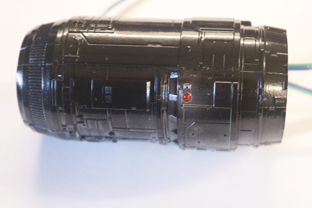
Preparing The Parts:
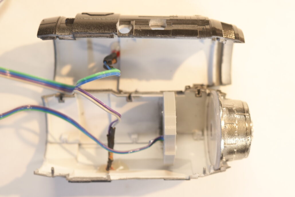
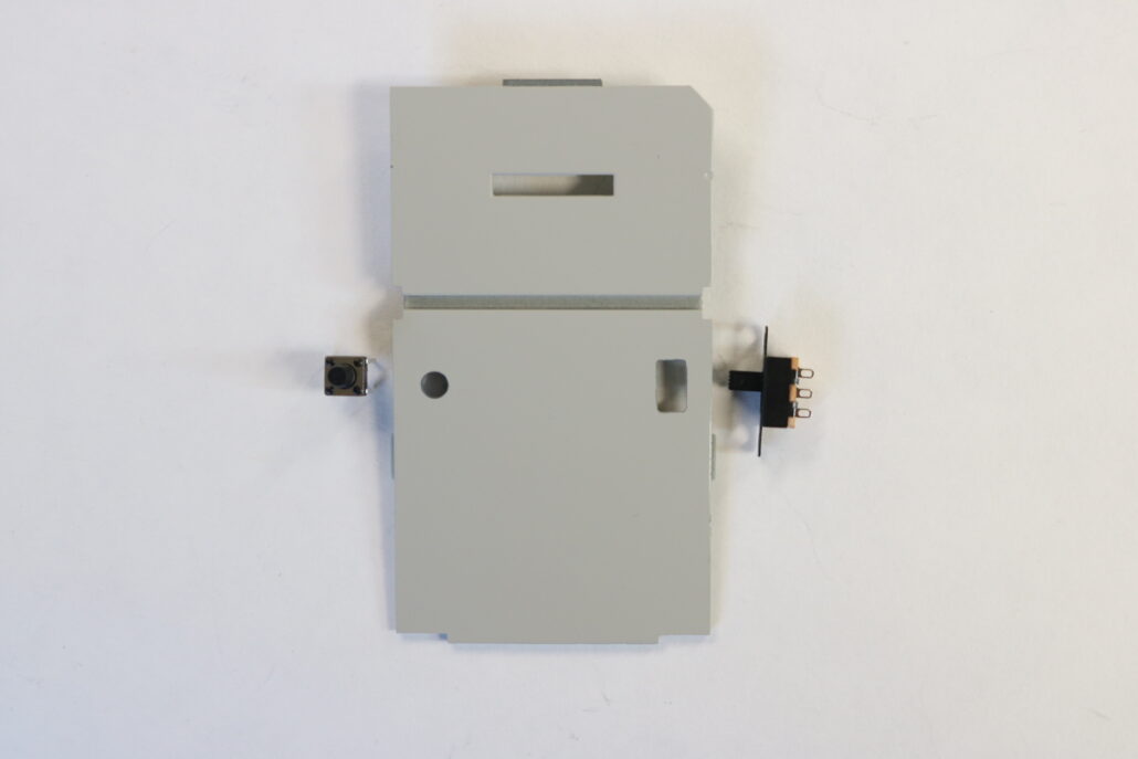
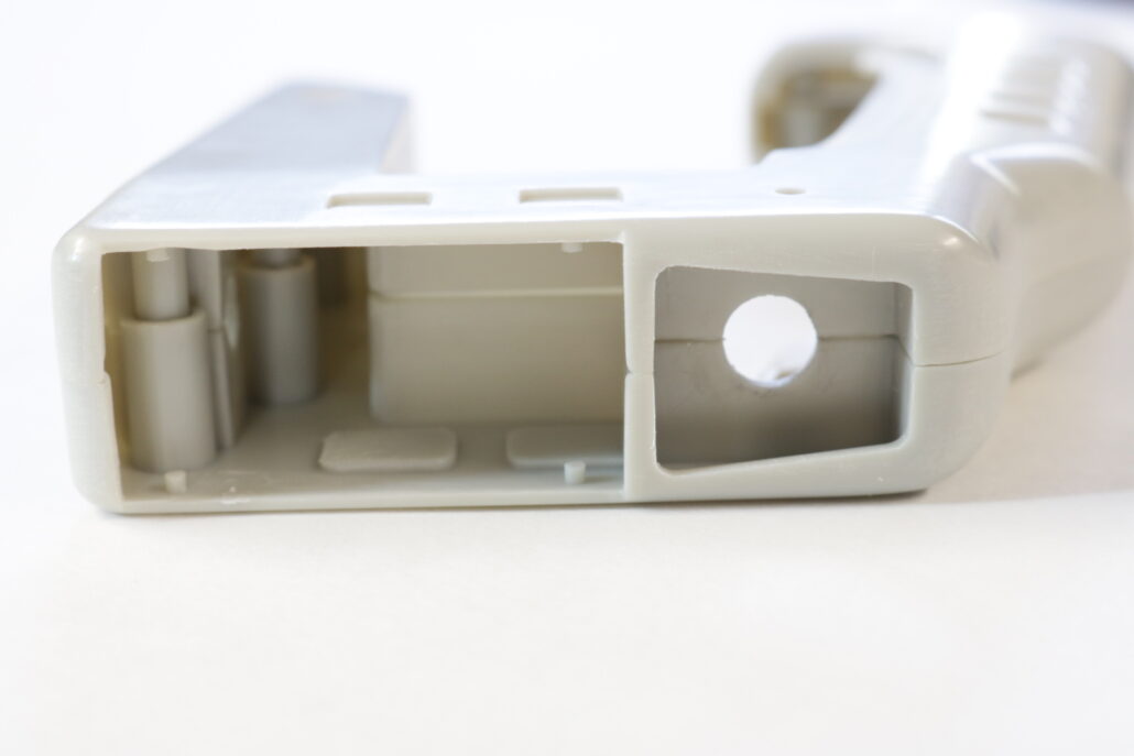
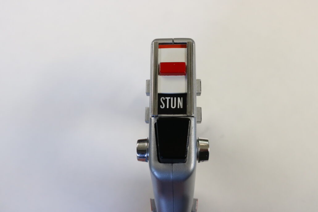
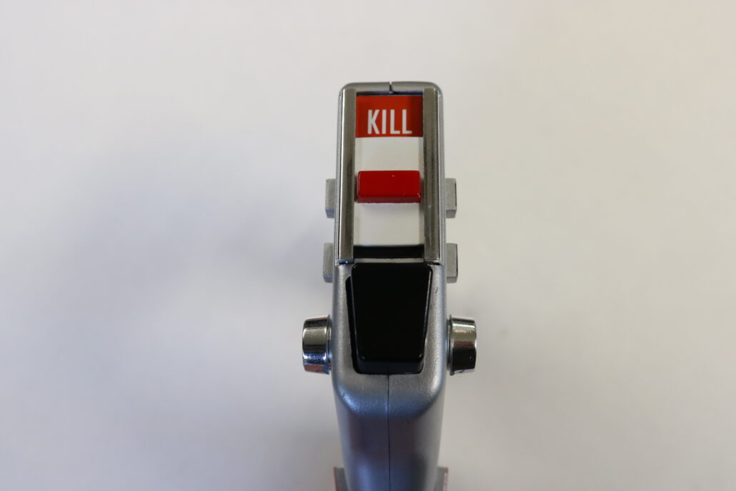
There are a few parts in the kit that will require modification for the lighting system. The four emitters will need to be drilled out on the back side to support a 3mm led. The housing that holds the emitter will also need to be drilled out & can be a little bit larger than the 3mm hole. If you are using the slider mode switch from season 1-2 you will need to cut a slot in the top of the slider mounting part. You must allow enough slack to move it freely back & forth. The firing momentary trigger switch will also need a hole drilled out in the center of the fire button. I also added a small piece of 9/32 tubing on top of the plastic button to extend the button height, giving it a little more range.
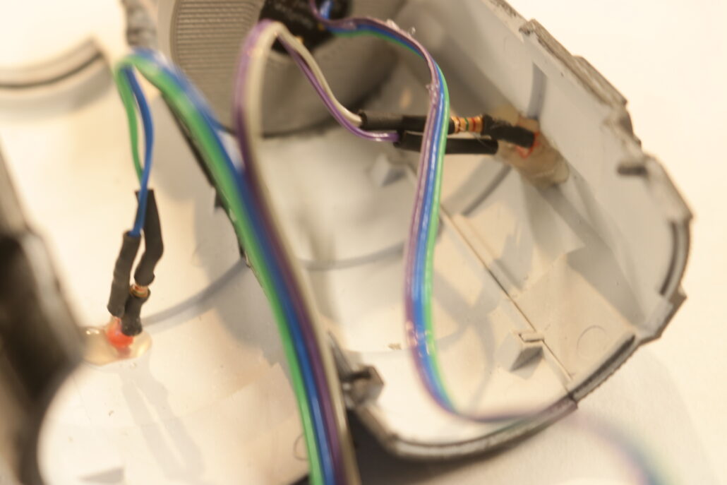
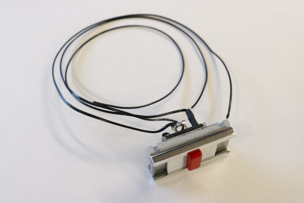
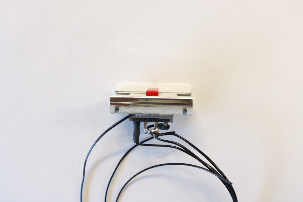
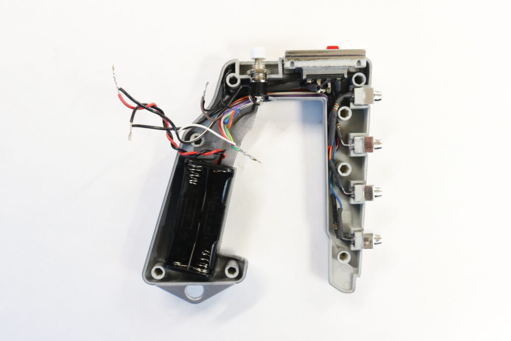
Prefabricating Led & Switches:
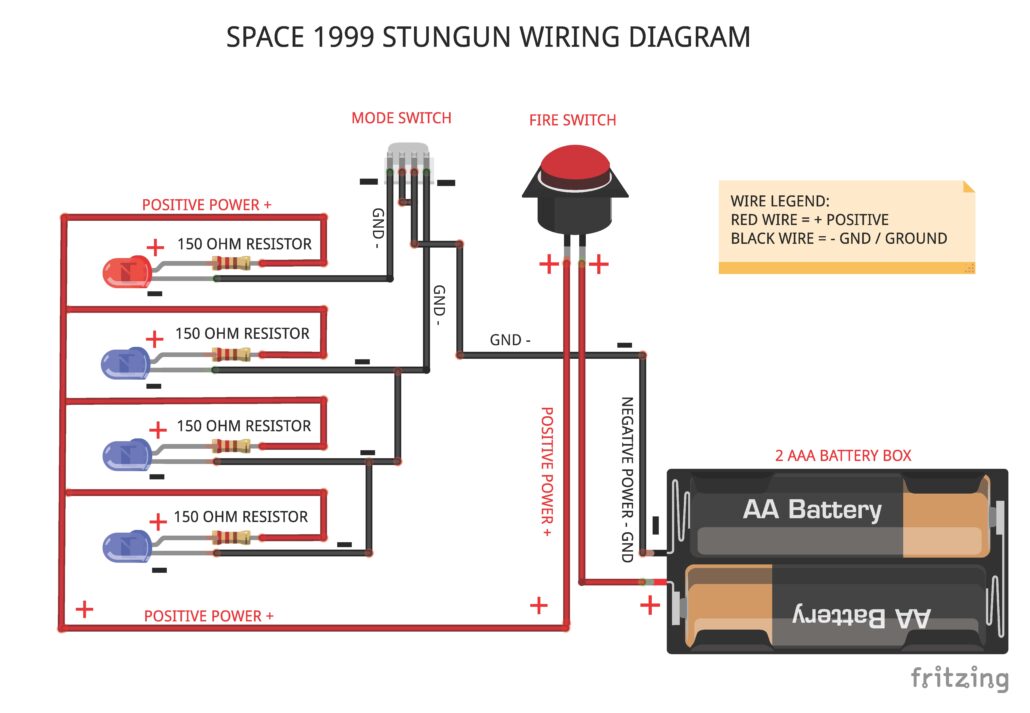
Once you have made the modifications to the model kit parts you can move forward & pre build the leds & wire up the switches. Its best way to start is with the leds first, each leds will require a 150 ohm resistor inline with each led, these are wired to the positive side of each led. The ground wires are tied to the slide switch if your using the selector switch for Stun or Kill. If your not using the selector switch you will tie all the grounds together and bring them to the ground side of the battery. The positive side is used to run the fire button or momentary switch only, all the leds are connected to the positives side and feed back to one side of the momentary. The other side goes straight to positive side of the battery hook up. Look at the wiring diagram for how to wire it.
First start by getting yourself familiar with all the model kit parts & where they are positioned to assemble the model. Second read all the information regarding the model lighting kit wiring diagram. There are only a few modifications that will need to be made for the lighting system.
Preparing The Parts:
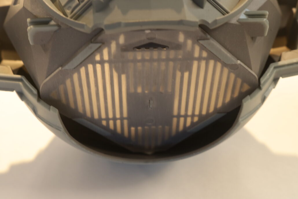
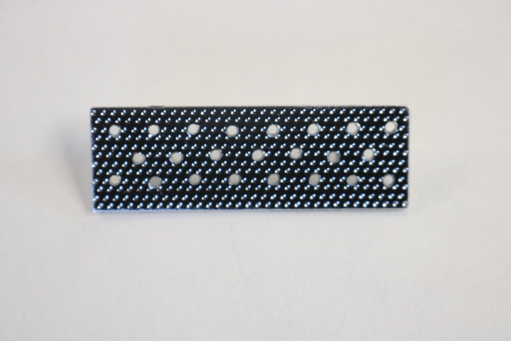
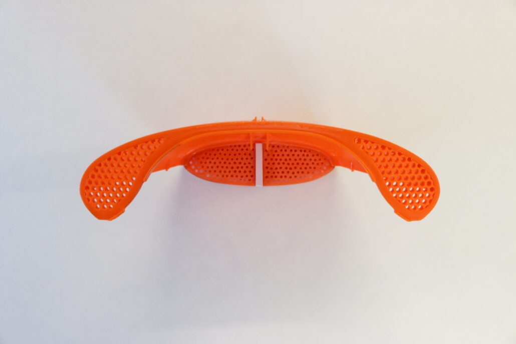
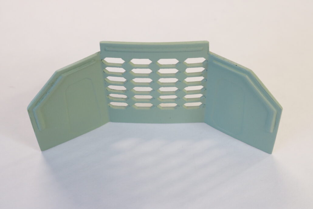
If you have the aftermarket parts from Yaymonsters than you will not need to perform this action. The three main parts that you will need to be drilled out are the Intake Grills, Rear Engine Grill & Interior Fusion Reactor wall. It is best to start with a small pinvise & #64 drill bit or 3/32″ bit. Drill out all the holes for the intake & engine grills, for the reactor wall I make 6 small holes around the diamond shape edge’s, then take a hobby knife & cut from hole to hole, poping out the center section. You will need a small set of files to clean up and trim to edge.
Diffusion Material:
After cutting out all the areas on the intake, engine & reactor wall you will need to back them with some diffusion material. The intake looks the best with the standard “White Milky Diffusion” cut to fit the tear drop shape and glue in place with some standard white glue. The rear engine looks the best with the 3D material, cut to fit and mount. I also preferred to use the 3D material on the reactor wall as well. Mount in place again using the white glue meathode. You will also need to scratch build a set of led brackets to hold the leds in place, I have provided a 3D file link as well if you want to print them on your own. Sorry to say the tear drop ones where done by scratch. When mounting your red leds it would be best to use the 150 Ohm resistor combo to power both the intake & engine effect for the brightest look.
Reactor Wall:
The back interior reactor wall requires a light box to be constructed to hold the light in. You will want to mount the blue led on the bottom of the box, having the led looking straight up. Use the 3D Diffusion material on the back side of the reactor wall, glue in place. It would be best to use the 220 Ohm resistors for effect in this area.
Cockpit & Passenger Area:
The front cockpit area has three main lighting features. One the main front screen & the two side monitors. You will want to use one red led for the front main screen, use a small piece of milky white diffusion material under the cut out of main screen. The two left & right side monitors is a warm white led mounted be hide diffusion material. The passenger are is also using one warm white led mounted on back wall above the doorway. It would be best to use the 1.5K Ohm resistors for a dimmer effect in these areas.
Dome Light:
The main center dome light is also going to use a red on light only. You will need to scratch build a led support for mounting the light above the walkway roof. It would be best to use the 220 ohm resistors for this feature. A small piece of the white milky material can be placed directly over the top of the led to make more cast light for the dome.
First start by getting yourself familiar with all the model kit parts & where they are positioned to assemble the model. Second read all the information regarding the model lighting kit wiring diagram. There are only a few modifications that will need to be made for the lighting system
Landing Ramp Lights:
You will need to drill out the 3 landing leg ramps lights to accommodate the 3MM warm white leds. It is best to create a centerline all around the area and then mark each landing well wall in center of each opening. Make a small mark and drill out the three holes. NOTE each landing well light will require an inline resistor.
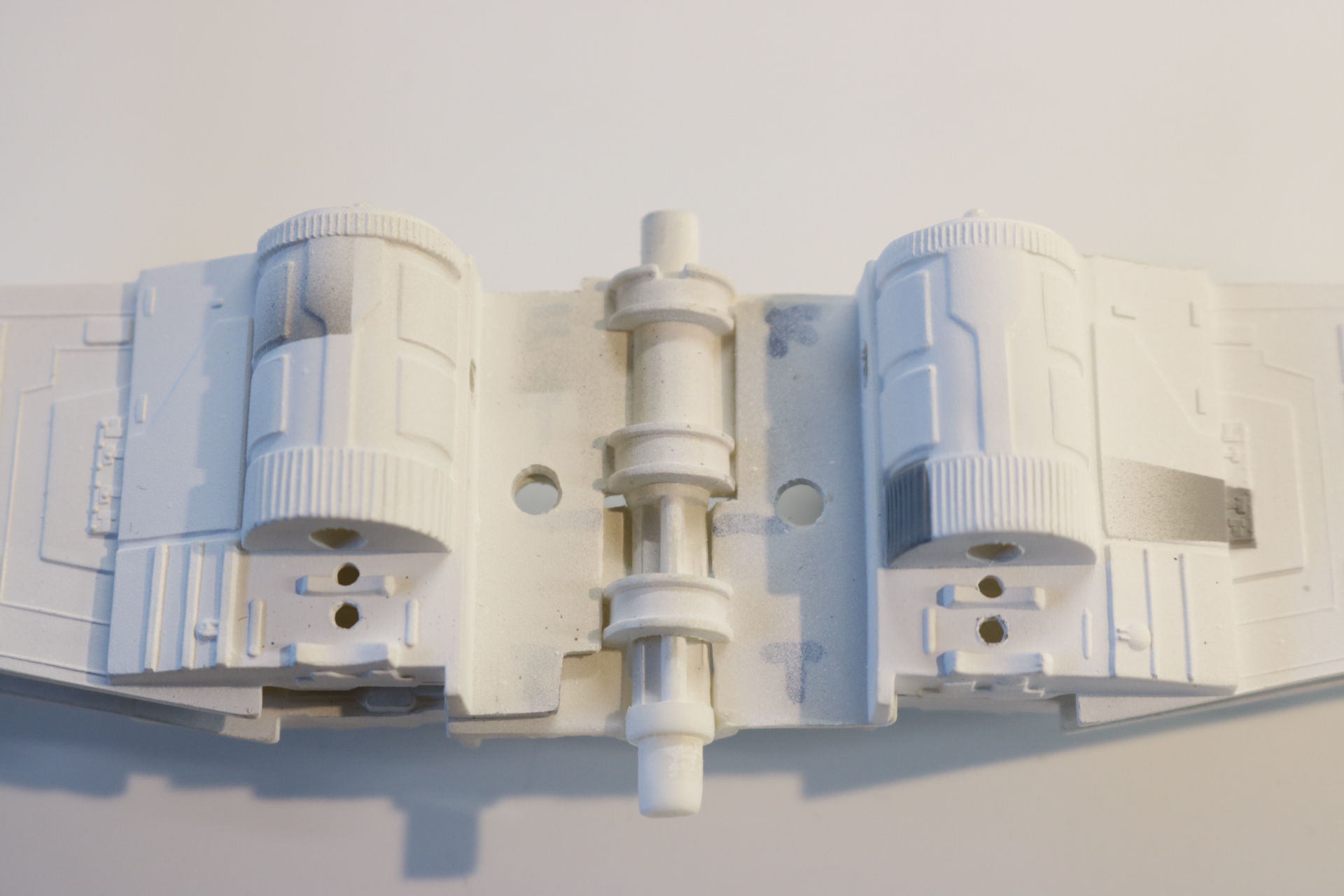
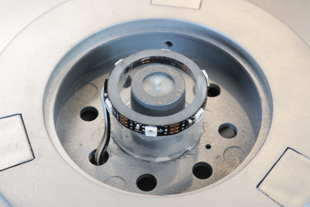
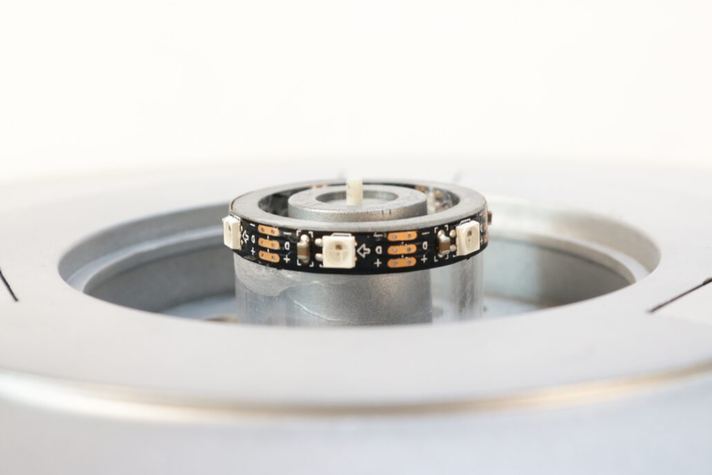
Strip Mount:
Next you will need to make a riser tube to support the strip system for the fusion core area. You will need to cut a piece of tubing 1”1/4 W X ¾”H and place it the center of stem part that supports the fusion core part, you want to be careful not the have the tube longer than the stem part since it will hang up the clear core part. Once the tube is centered & mounted in place pre wire your 3 wires to the strip make sure that the directional arrow is pointing towards the run of leds. NOTE You will not need to use an inline resistor for the strip it will be driven direct for the 5V + from the circuit board.
Wiring Diagram:
You will not need to use an inline resistor for the strip it will be driven direct for the 5V + from the circuit board. It is also important that you make the digital output wire from port 5 connect to the strip marked Din & connect all GND or ground runs together. The 9V battery & circuit board can be mounted in the upper dome area but momentary mode switch & master on/off switch will need to placed either on the lower surface of the model or hidden in the leg wells. It is best to pre build & paint as much as the model as you can before installing the electronics.
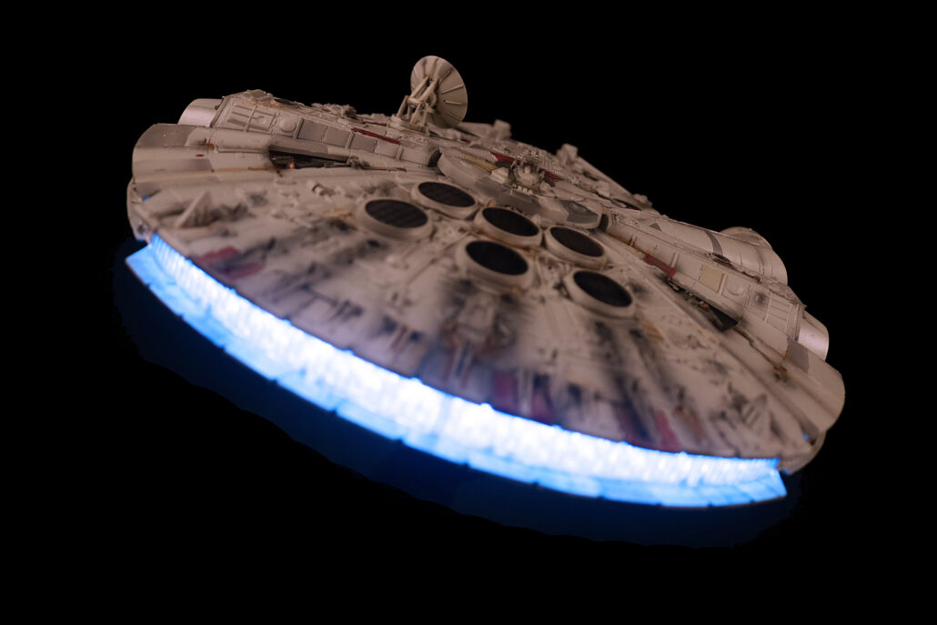
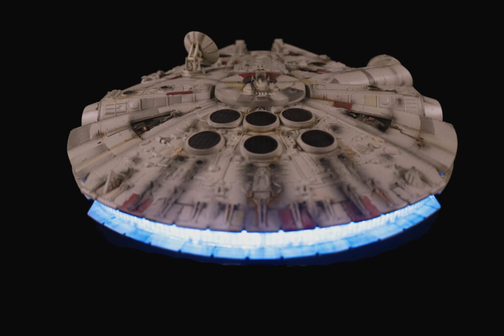
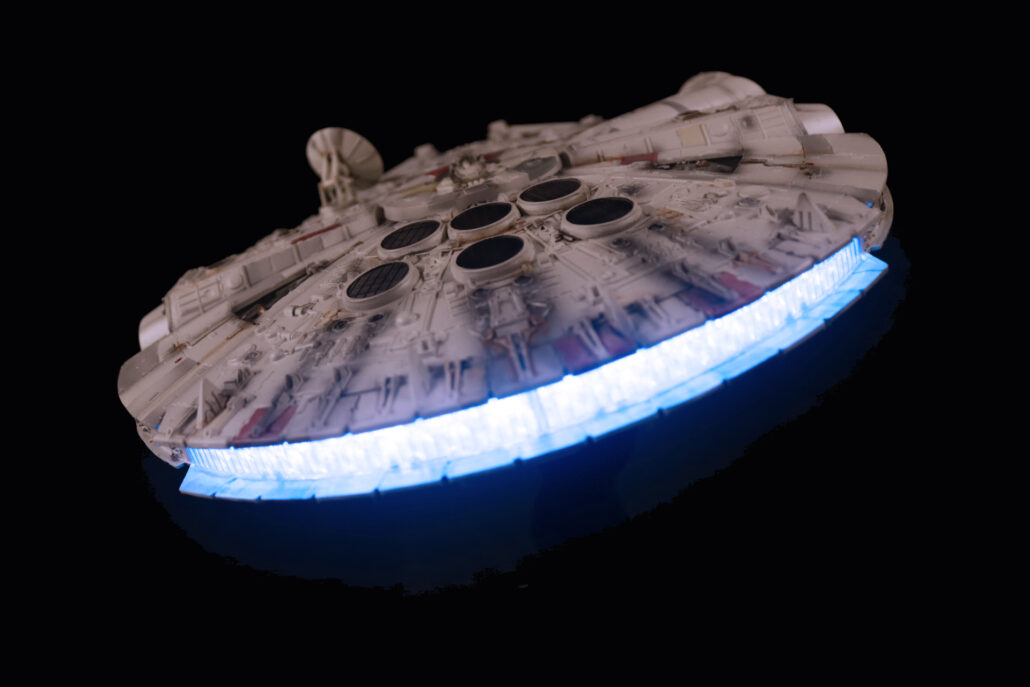
Finished Model:
After getting all your electronics in side the model run the system for a minimum of 5 minutes before making any finial close up. It is always a good rule to allow access in to any electronics for the possible of burnout or replacement of a bad led. If there is any questions you are having I can always be reached at randy@voodoofx.com, thanks for your interest in this build blog.
http://www.voodoofx.com/wp-content/uploads/2021/08/C57D-Finish-1-Crop.jpg6561716Randy Neuberthttp://www.voodoofx.com/wp-content/uploads/2023/12/VFXGEAR1-300x248.pngRandy Neubert2021-08-30 07:50:122023-11-12 12:11:27C57D Space Cruiser Lighting Kit
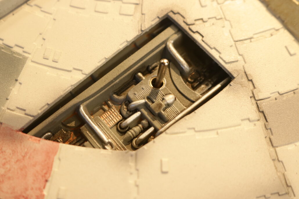
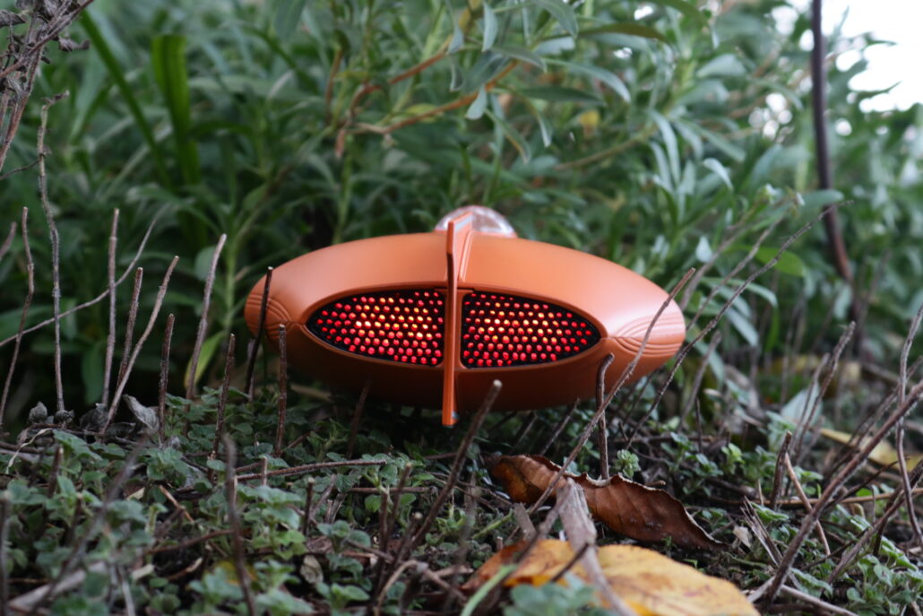
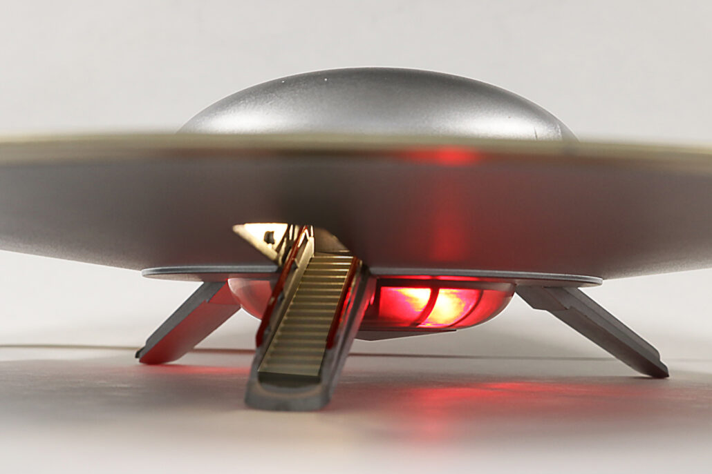
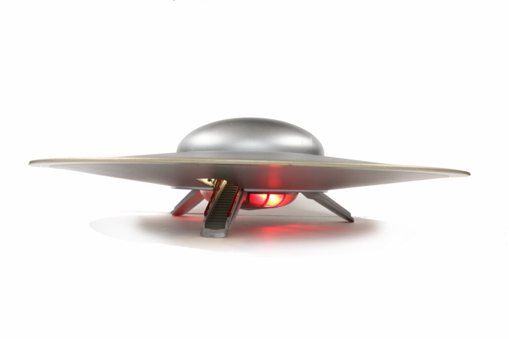
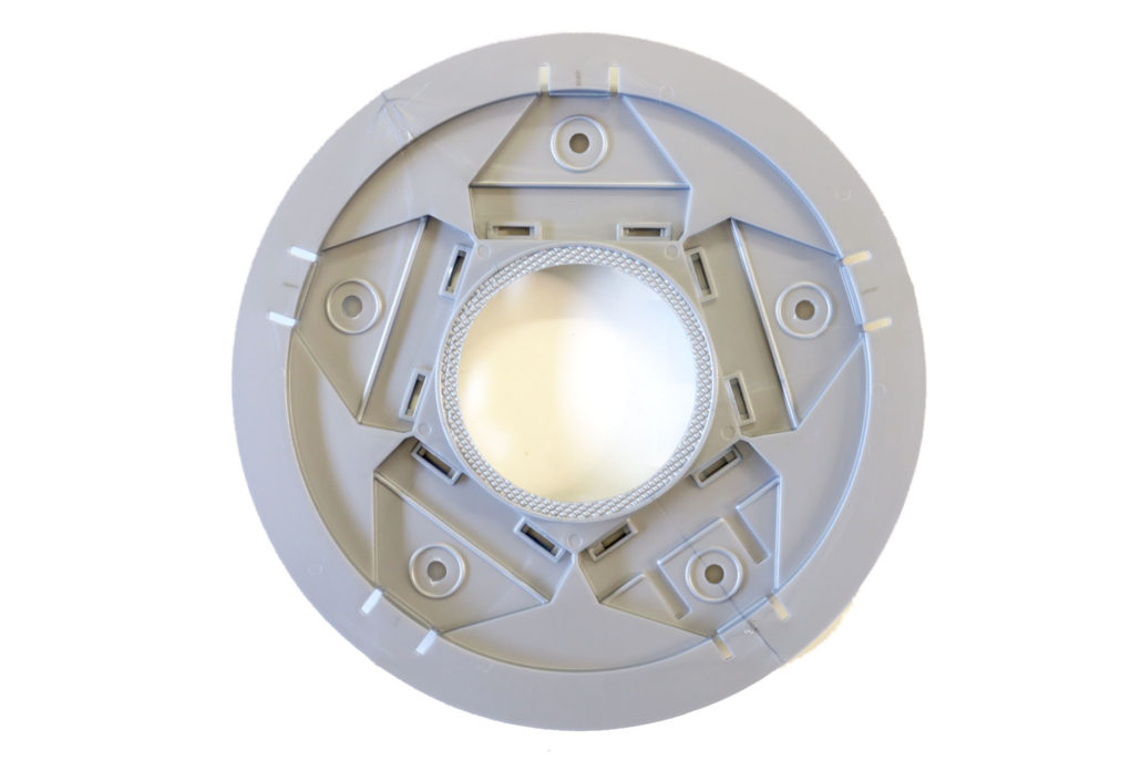
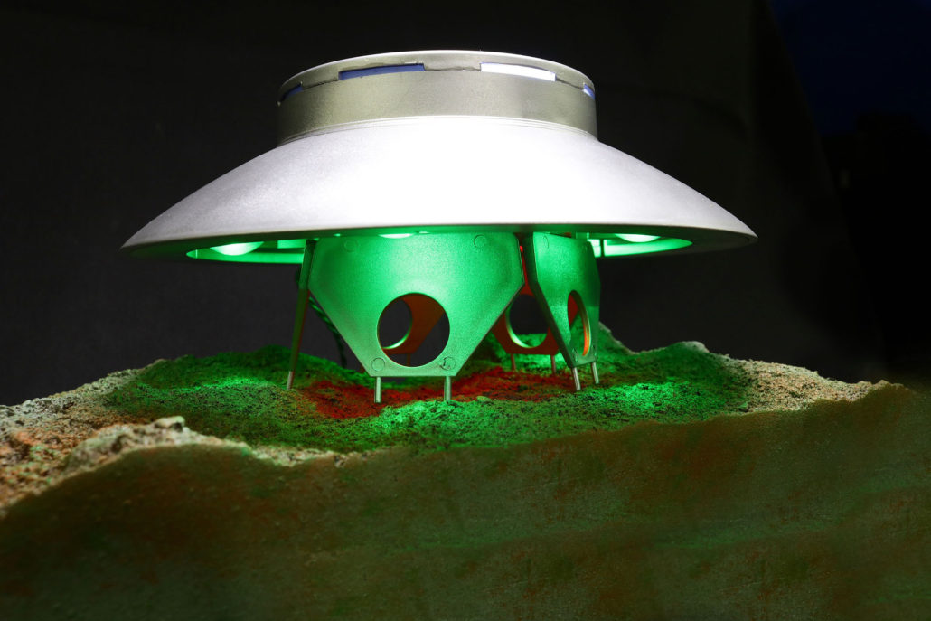
In this blog I will be going over the basic building modifications & fit work to support the Invaders UFO lighting kit. Please remember that due to the small scale of the model kit, the interior is unsuitable for use in the fully-lit version… however, if only lighting the five outboard dome lights you may be able to also light the interior.
Note: VoodooFX has no control over third party aftermarket parts & accessories availability.
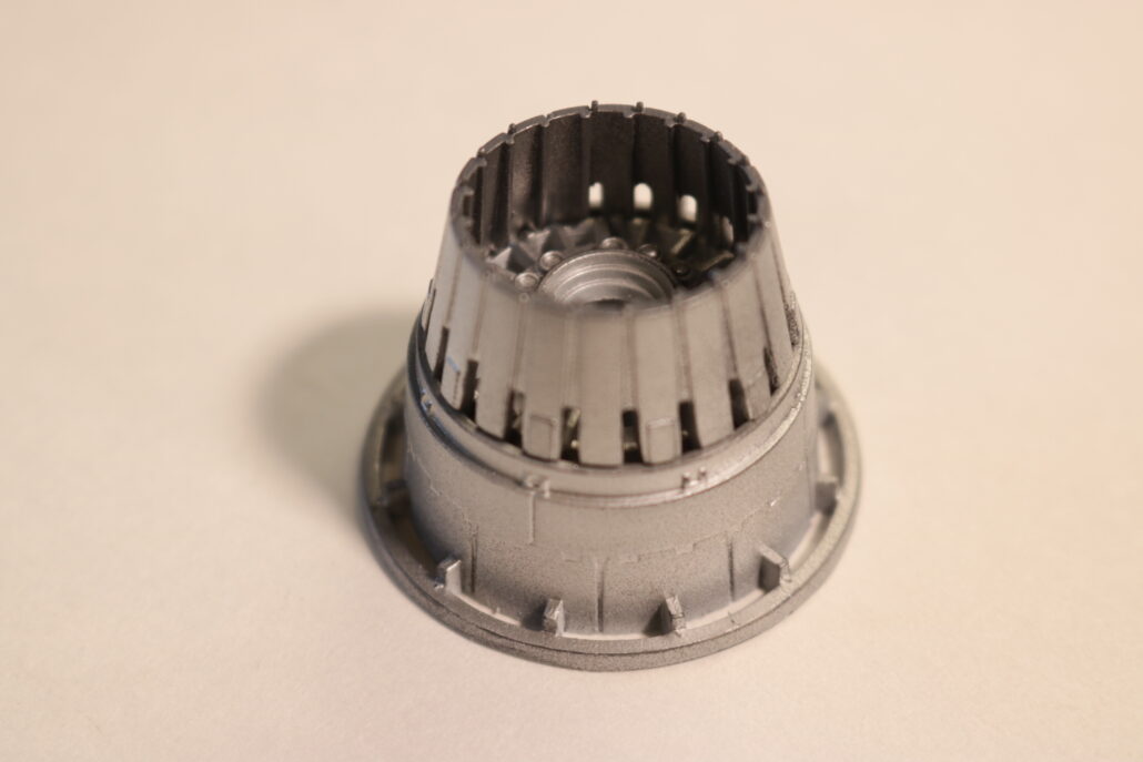
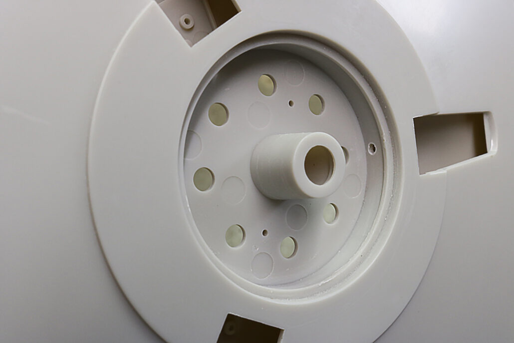
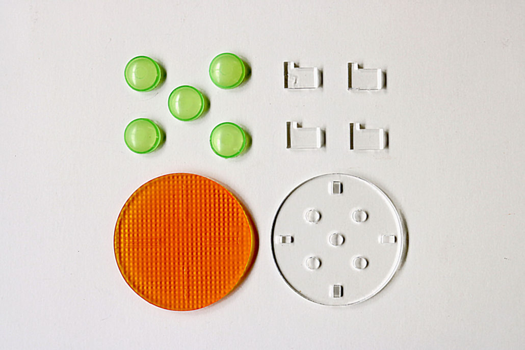
Yaymonsters lens & leds support kit
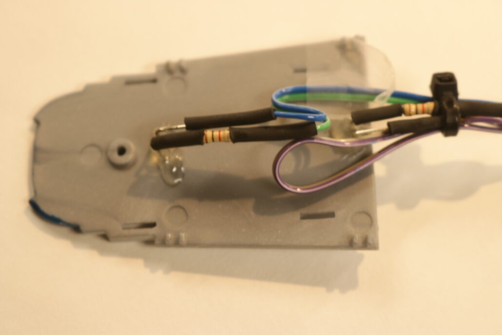
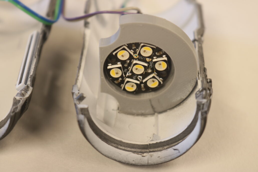
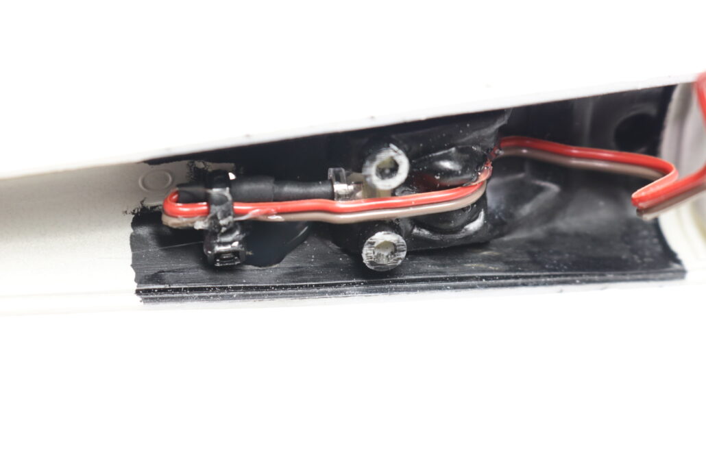
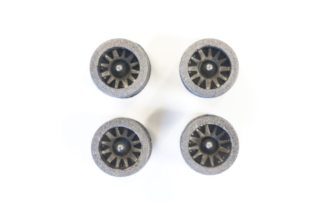
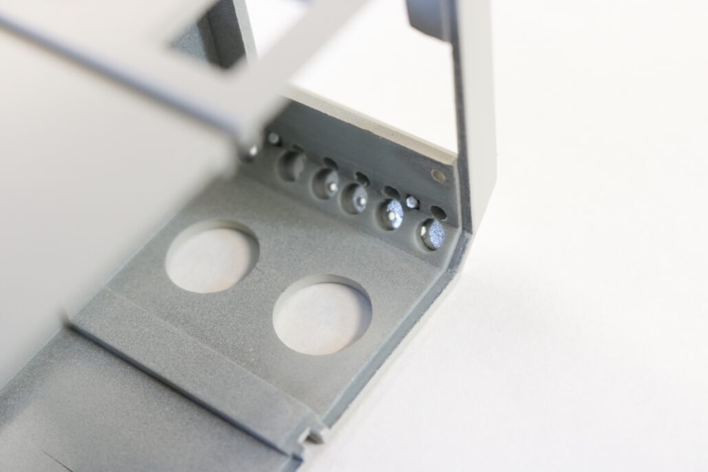
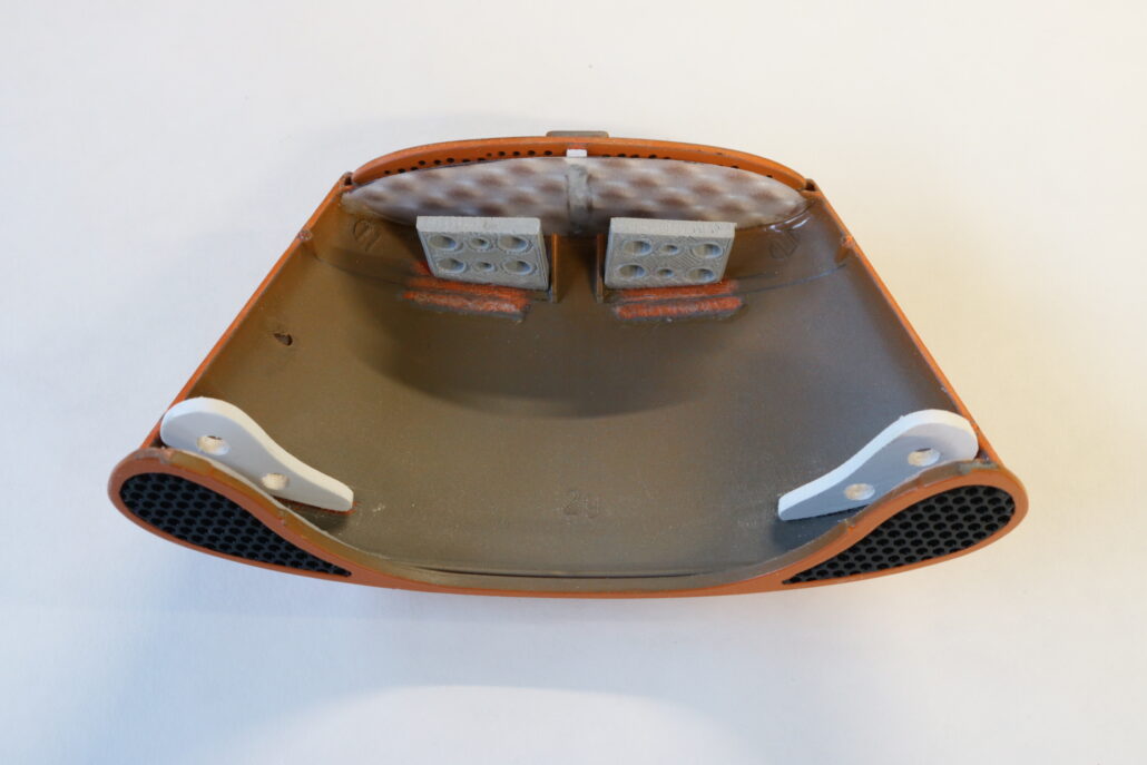
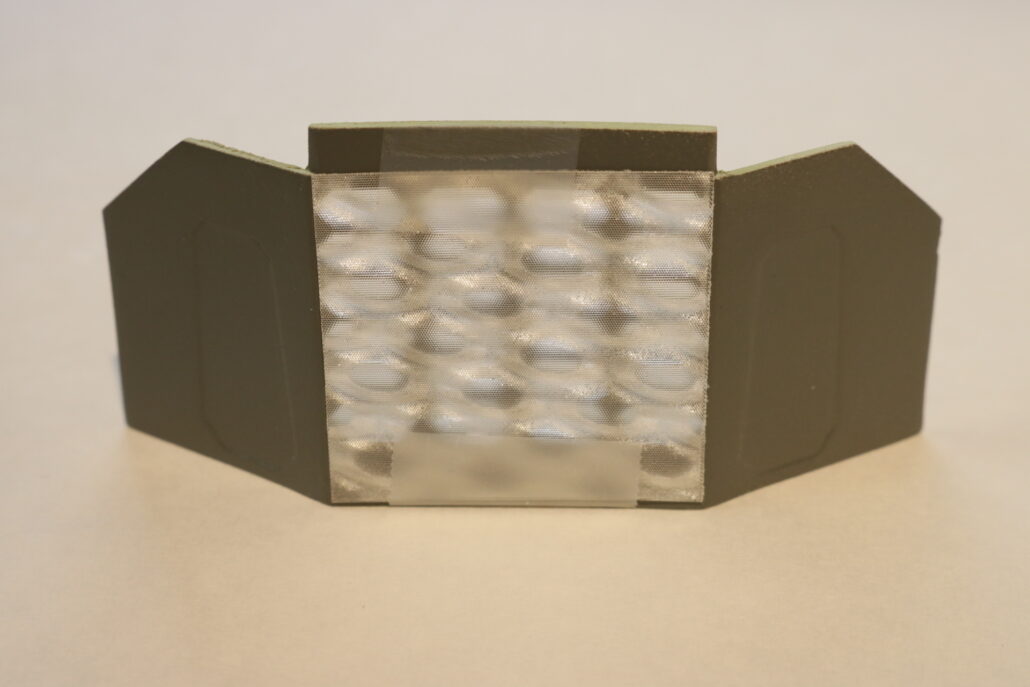
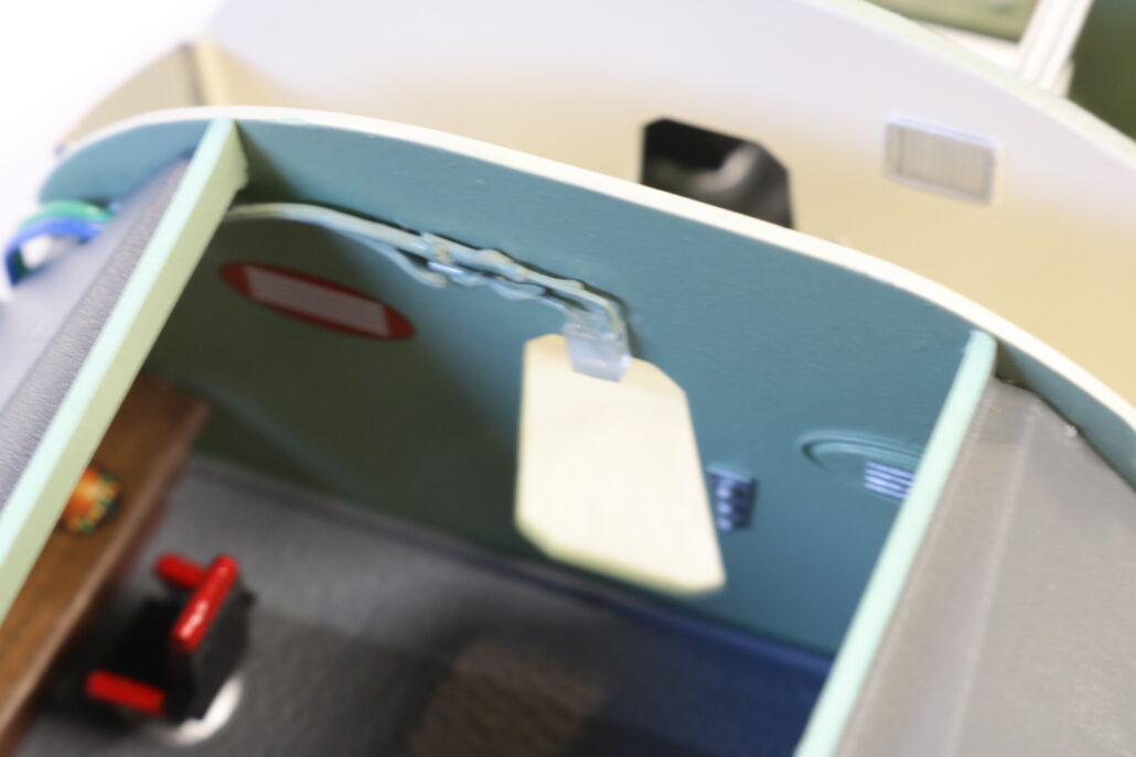
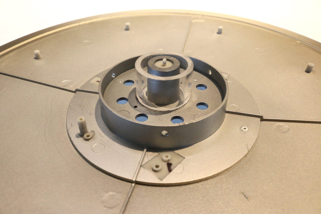
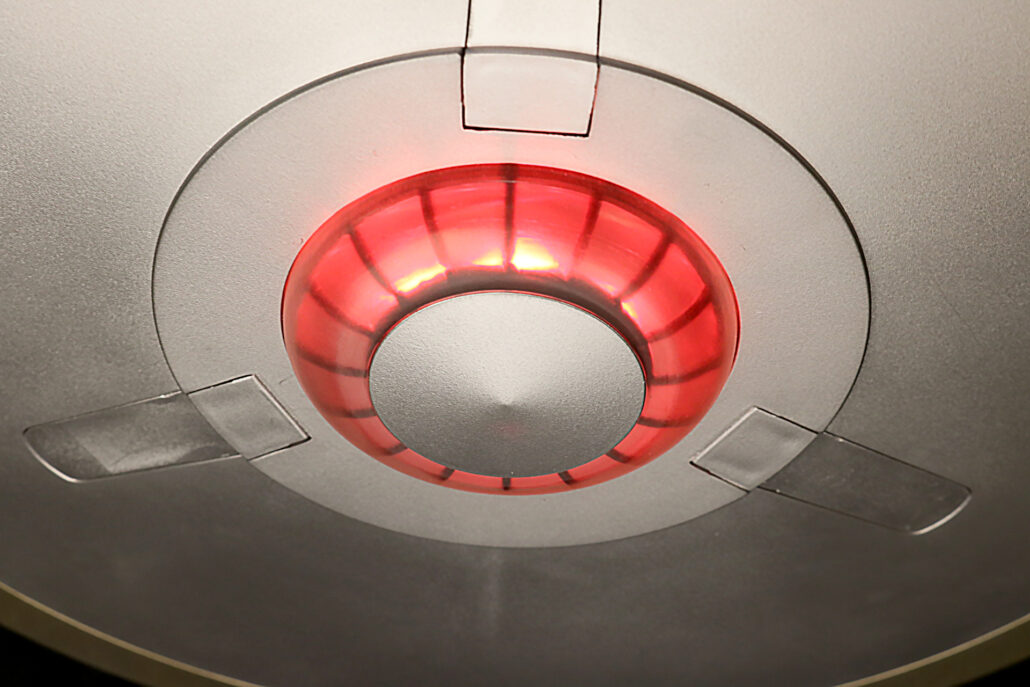
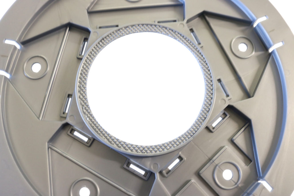
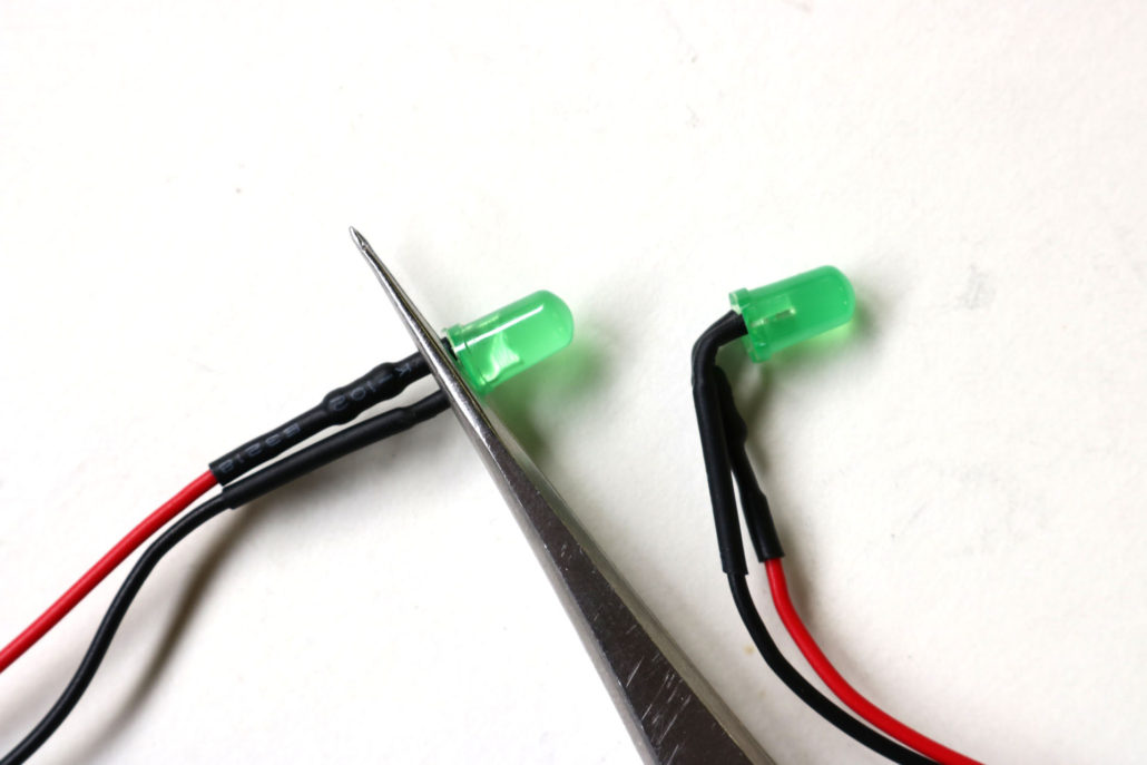
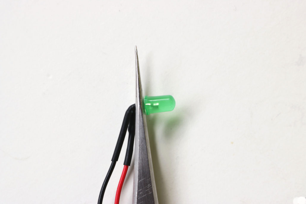
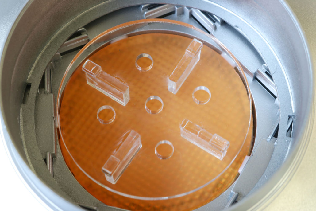
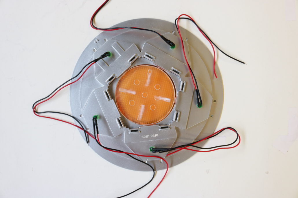
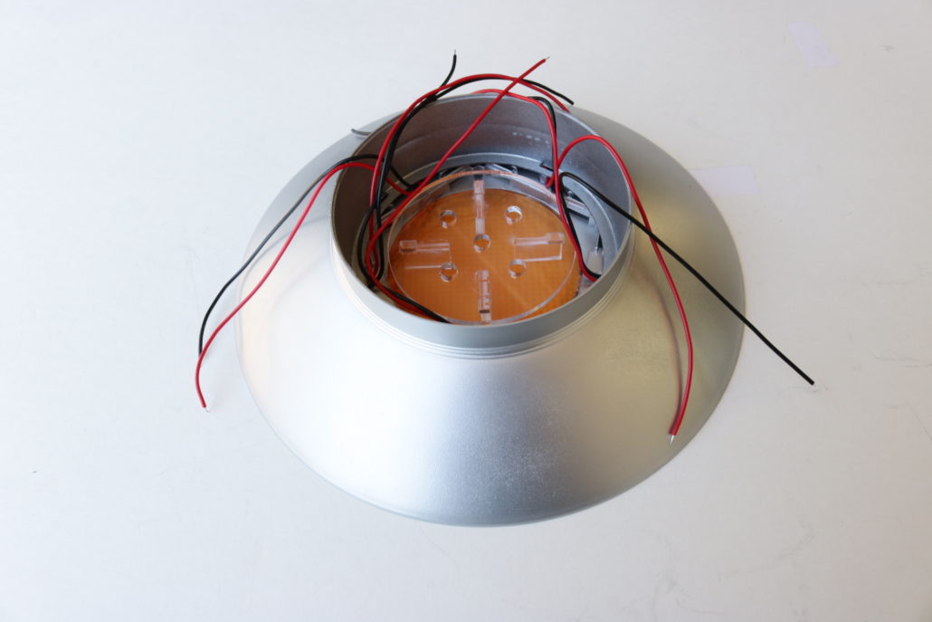
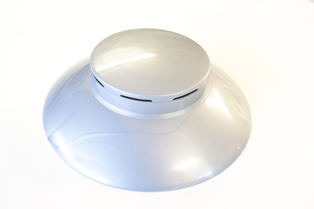
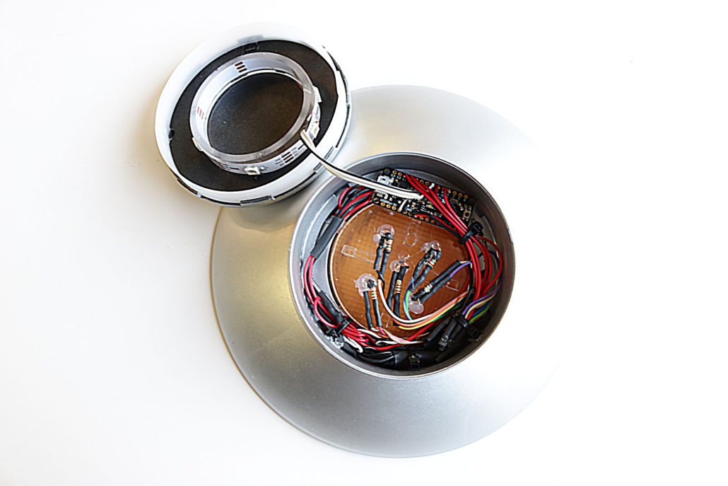
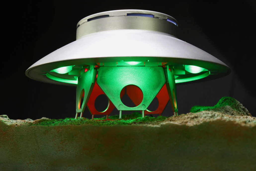
First getting started, the main central engine area will need to be cut out to support the new lens part. You will want to leave a small ledge (around 3/16″) of the original engine grid to rest the new lens part on, this will be mounted on the inside of the main engine chamber. The five outer domes will also need to drilled out at 5mm to support the green LEDs. The green LEDs will need no in-line resistor, as they are already pre resisted. (NOTE) The green LEDs will need to bent at a 90 degree angle to save as much room as possible.
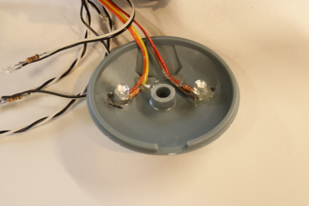
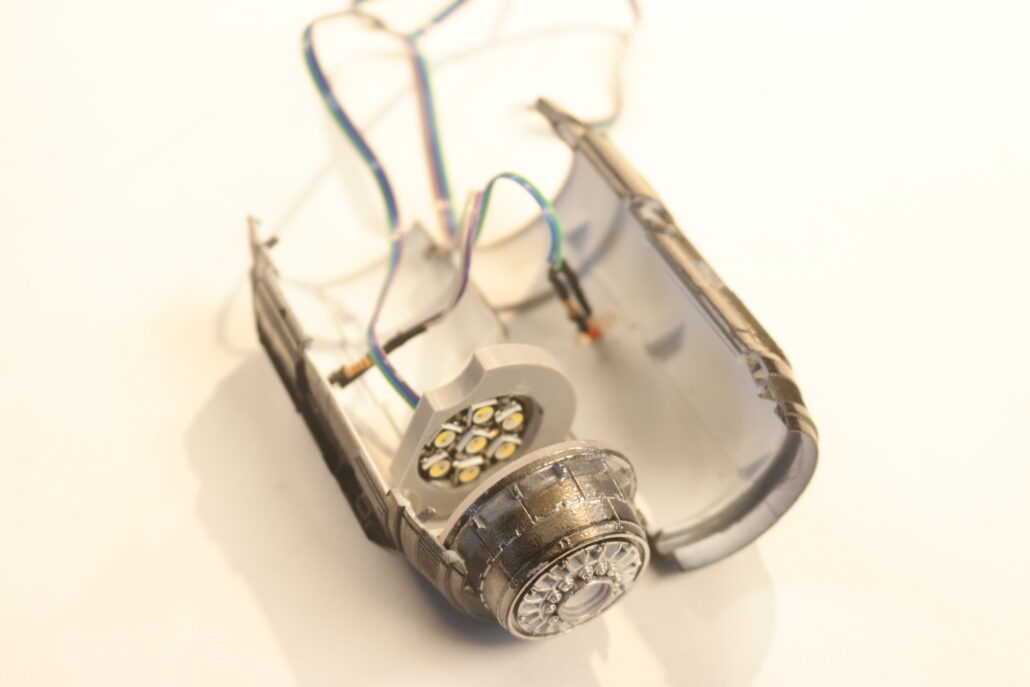
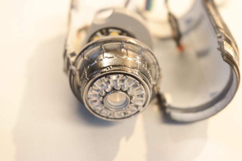
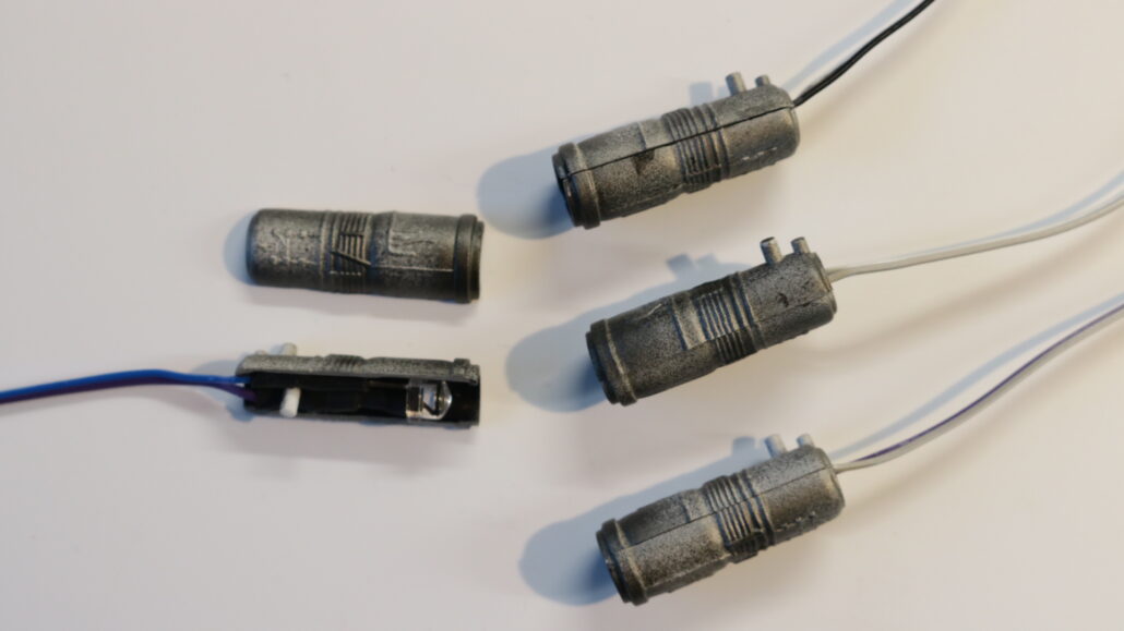
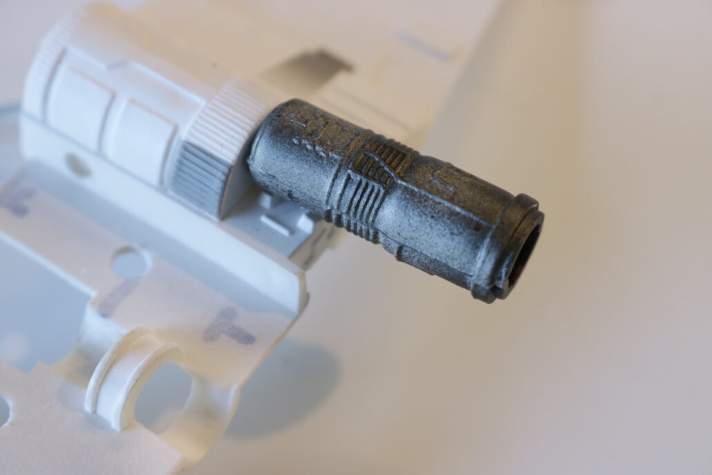
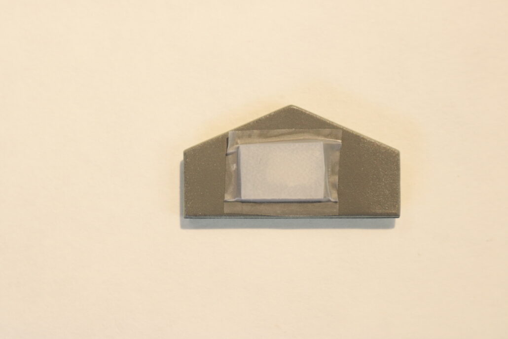
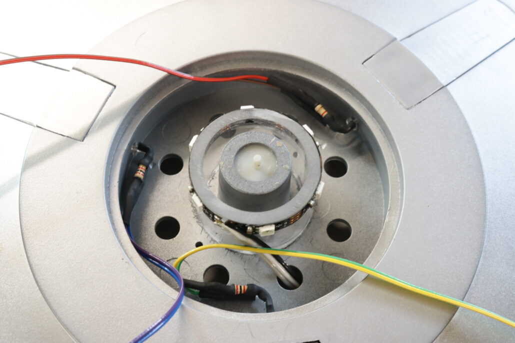
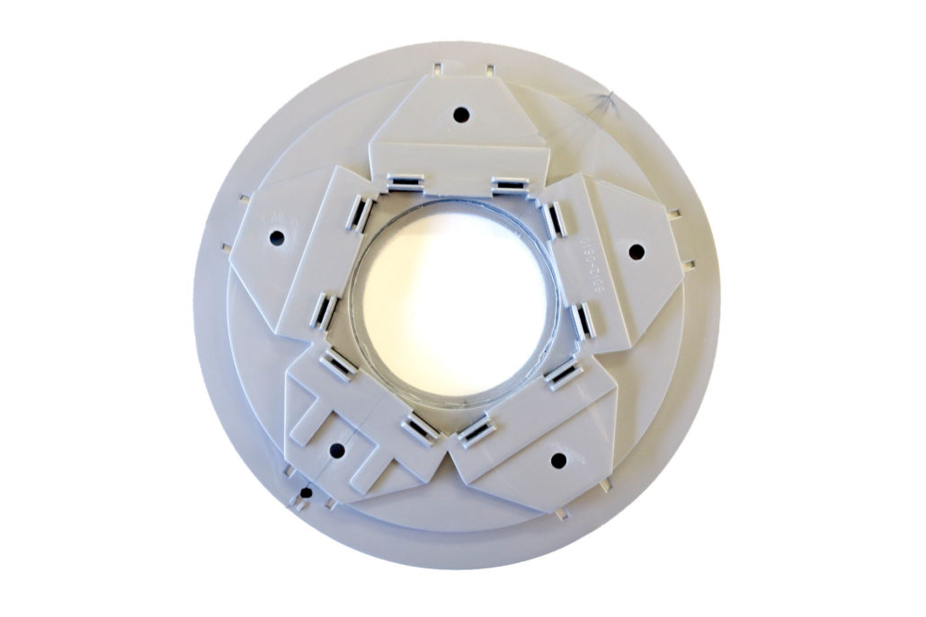
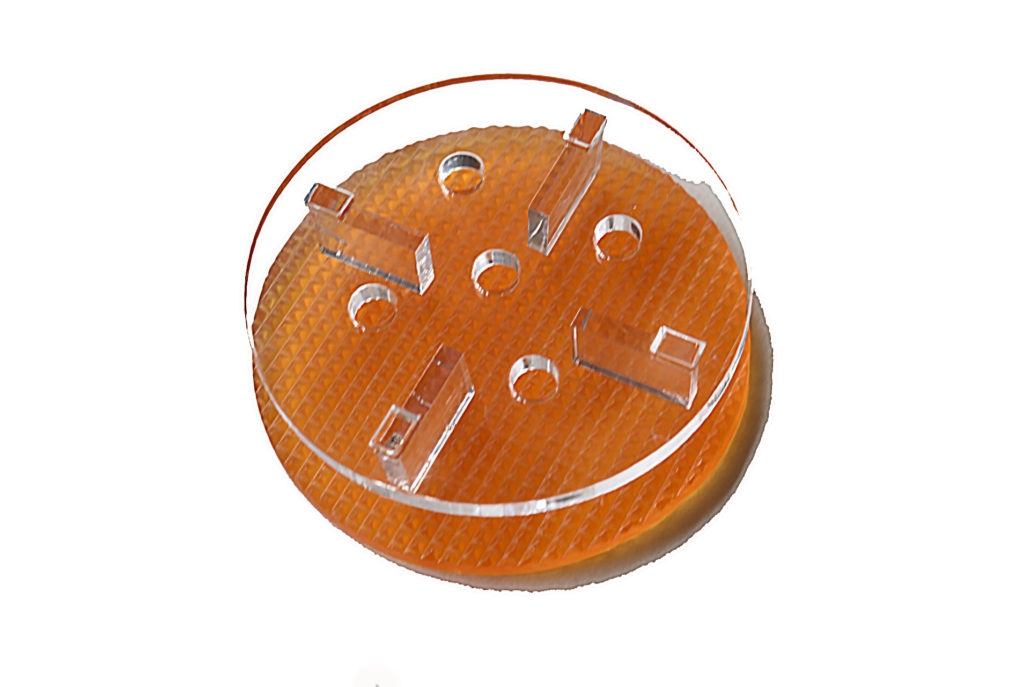
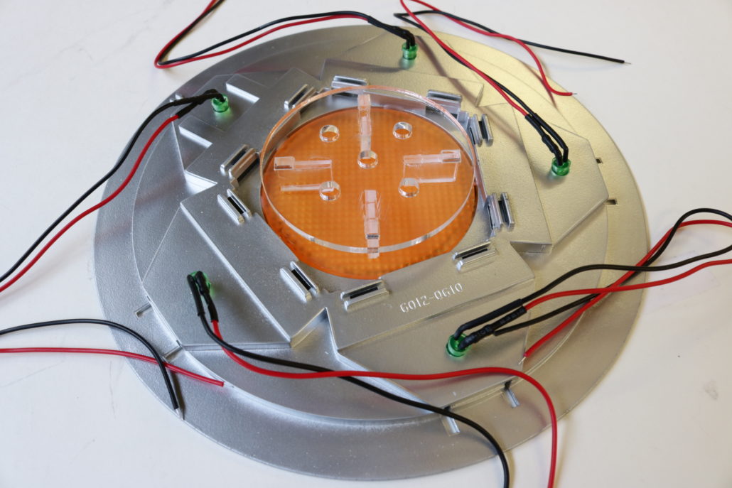
After pre-bending all the green LEDs, they can be threaded into the 5mm holes you already pre drilled for the domes. When mounting the LED, you will want to test them with the green dome lens to make sure that they don’t get pushed too deep in the hole, making them bottom out on the lens cover. Use a small amount of hot glue on the LED for permanent mounting. It’s a good idea to black out the LEDs to help prevent light leaks throughout the model. This is also an opportune time to get the main engine lens & LED support bracket built. Prebuild the clear acrylic support first, glue together & let dry. Mount the lower lens (with the ‘bumpy’ side down) towards the bottom of the model. Use either white glue or clear silicone to mount the lens, and let fully dry. After drying, mount the LED support on top of the lens, and check the cross pattern for alignment.
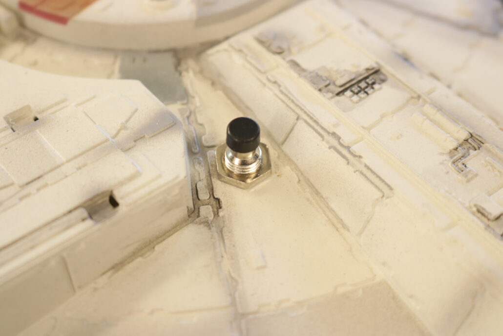
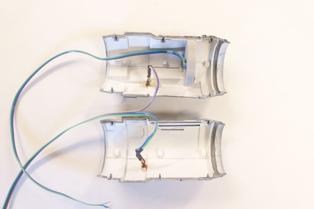
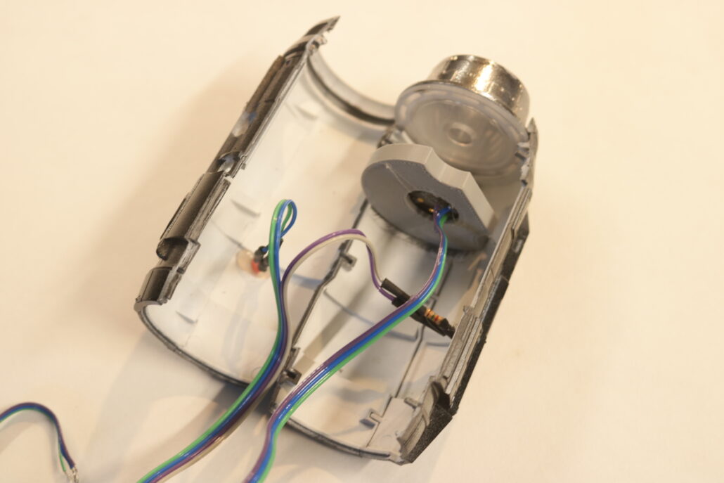
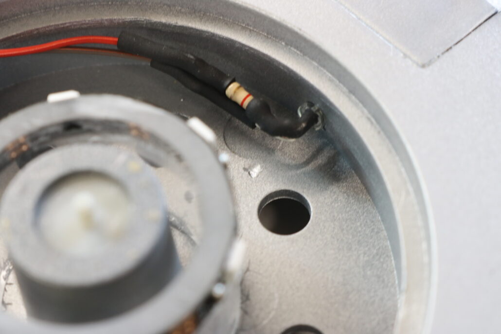
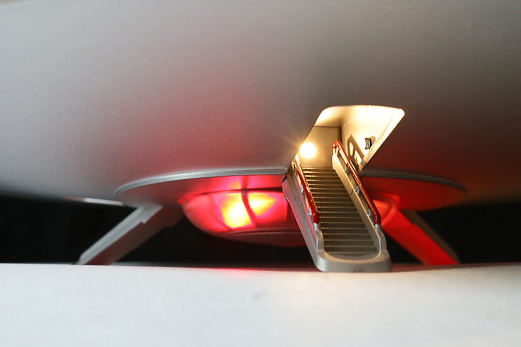
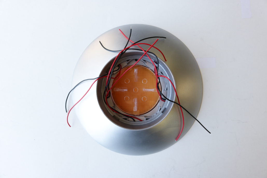
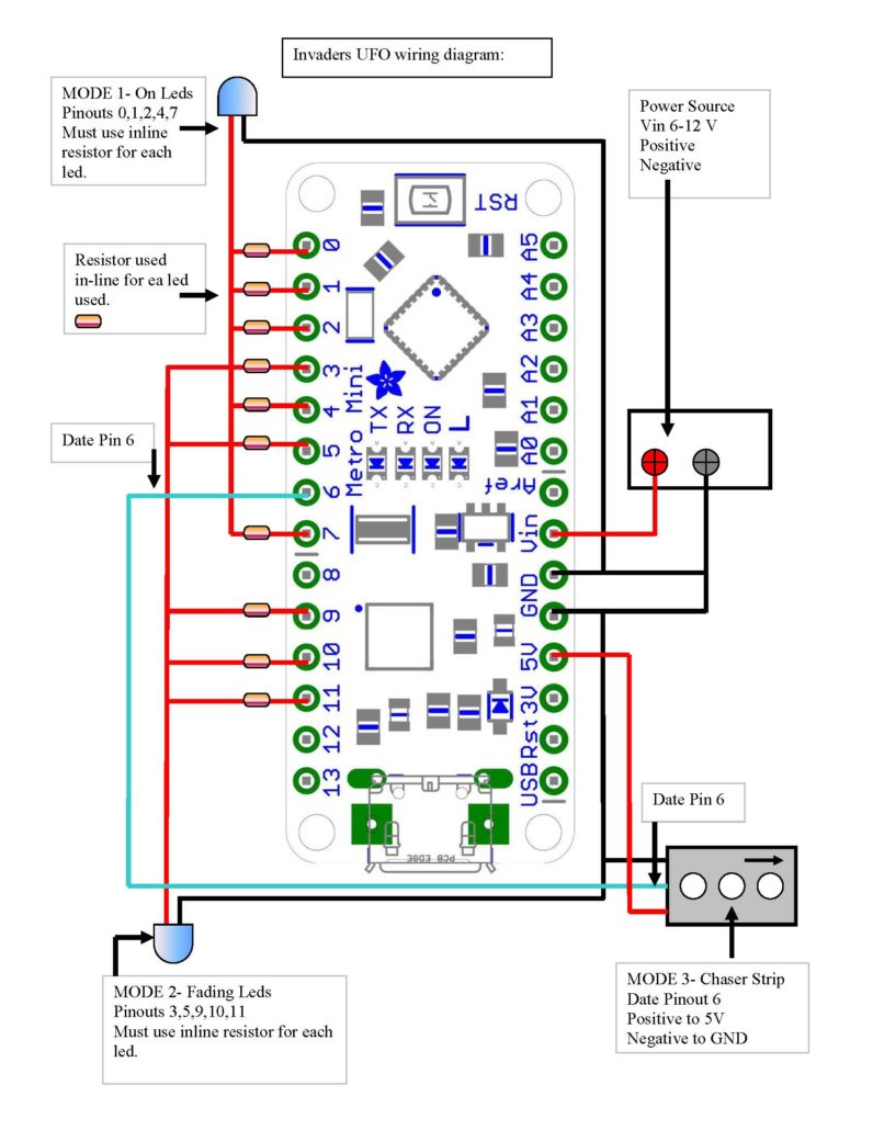
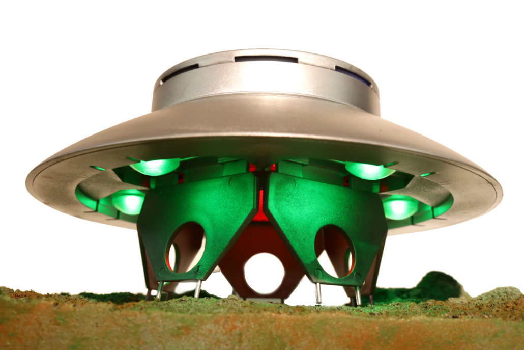
The dome lights can be either tied into direct power, or can be hooked up to the master circuit board using pinouts 0,1,2,4,7. Further info on the circuit board layout is provided later in the article. After mounting lens and LED supports, test all the dome lights for operation. Carefully route the dome lead wires into the center of each landing leg, via their mounting tab. Keep in mind, you will need to make a small “S” turn in the wire to prevent kinking of the LED. Use a small amount of hot glue to hold the wires in the center. You may now mount the upper half of the model to the base plate.
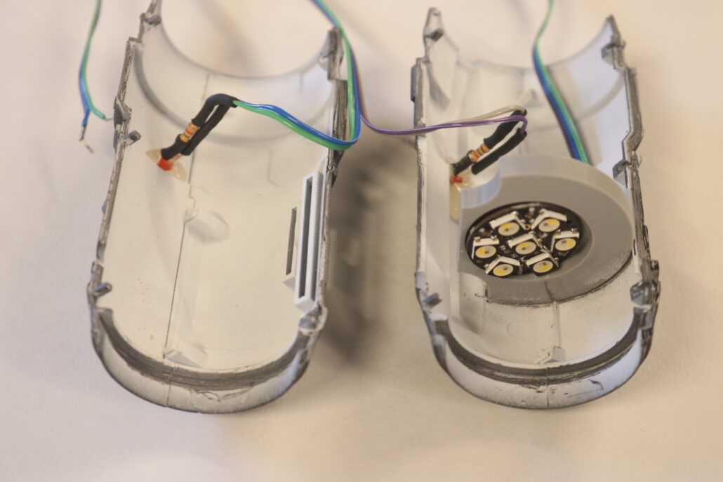
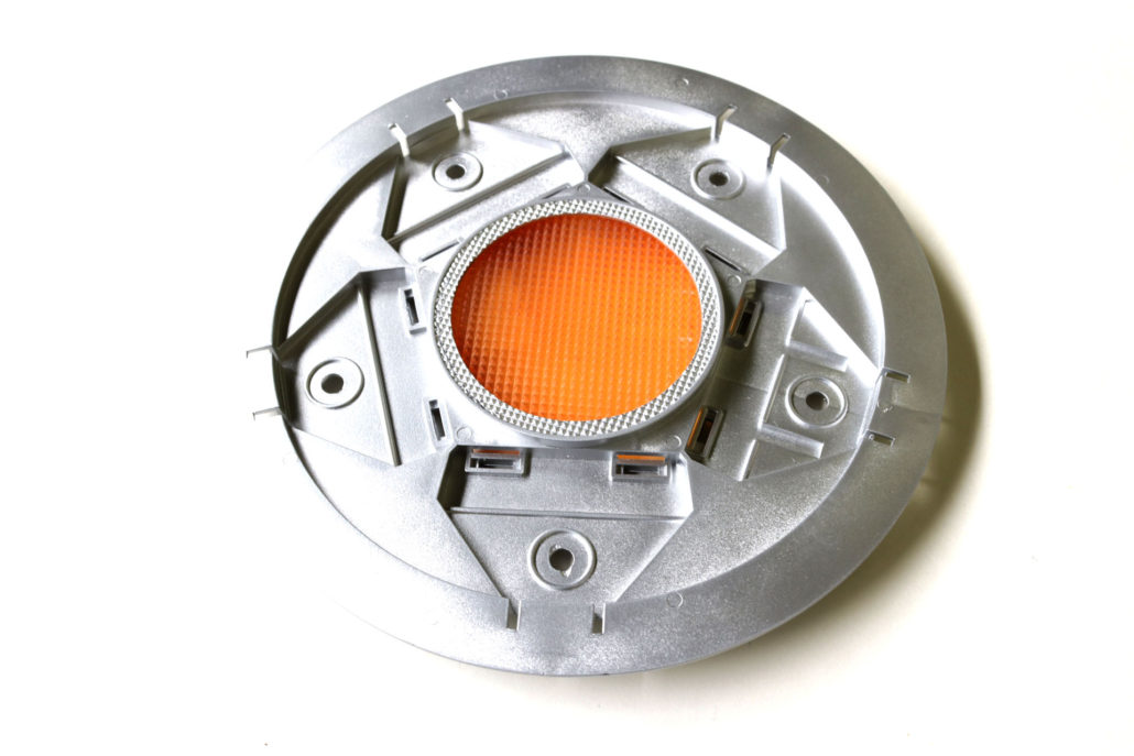
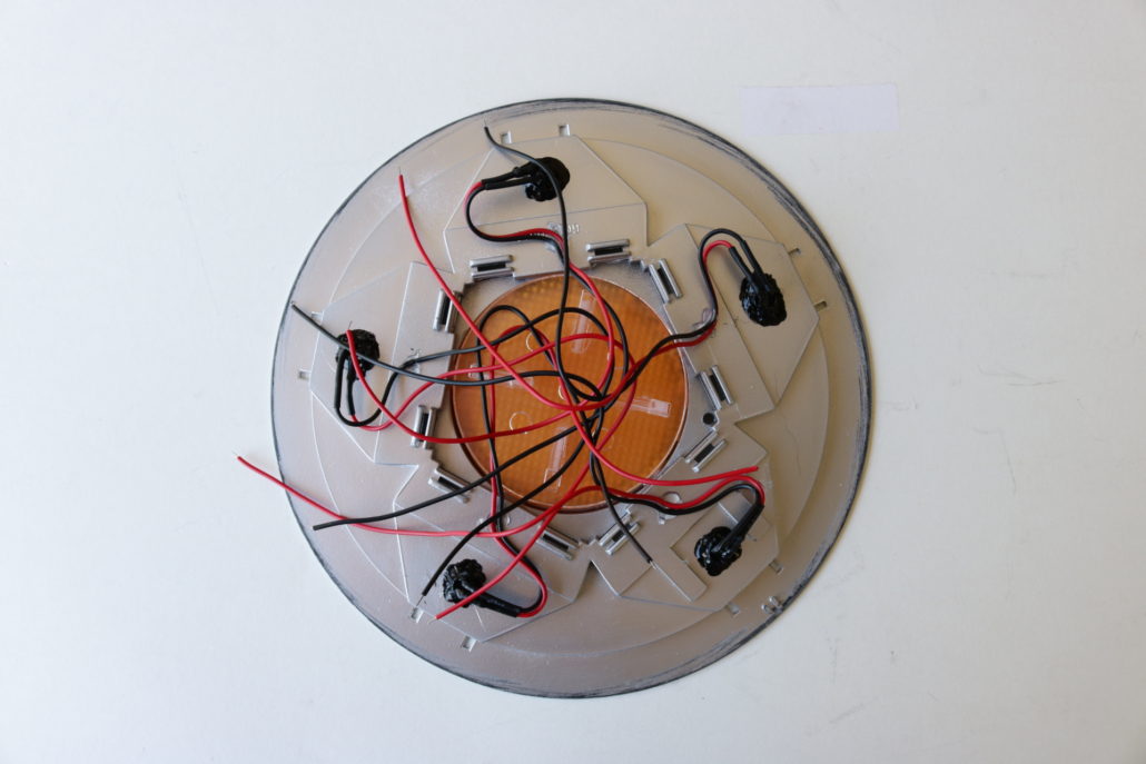
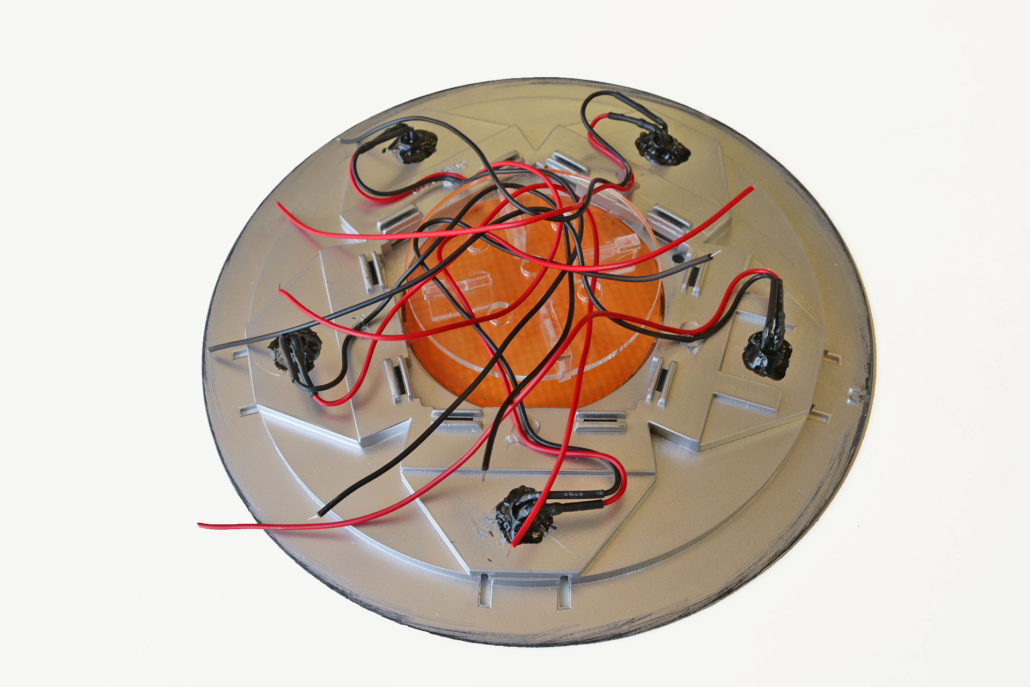
The next step is mounting the five engine LED’s. These LED’s will require a inline resistor on the positive side of the leads. The LED’s will also need to be bent at a 90-degree angle for fitting purposes. The engine lights are powered directly to the circuit board using pinouts 3,5,9,10,11. Again, further information on the circuit board layout is provided later in the blog. Once you have pre-fabricated the LED’s with their resistors, test each LED for operation. Carefully bend each LED at a 90-degree angle & mount to the LED support bracket with a small amount of glue. Run wires long outside the top of the model, these will be cut down & soldered to the circuit board in the final assembly.
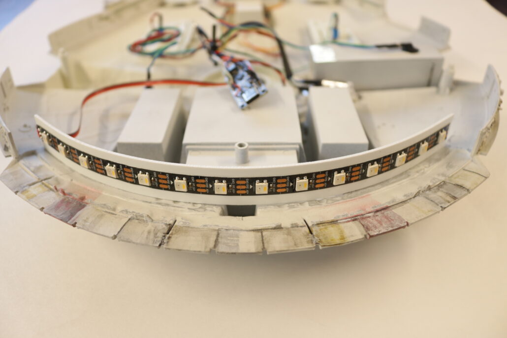
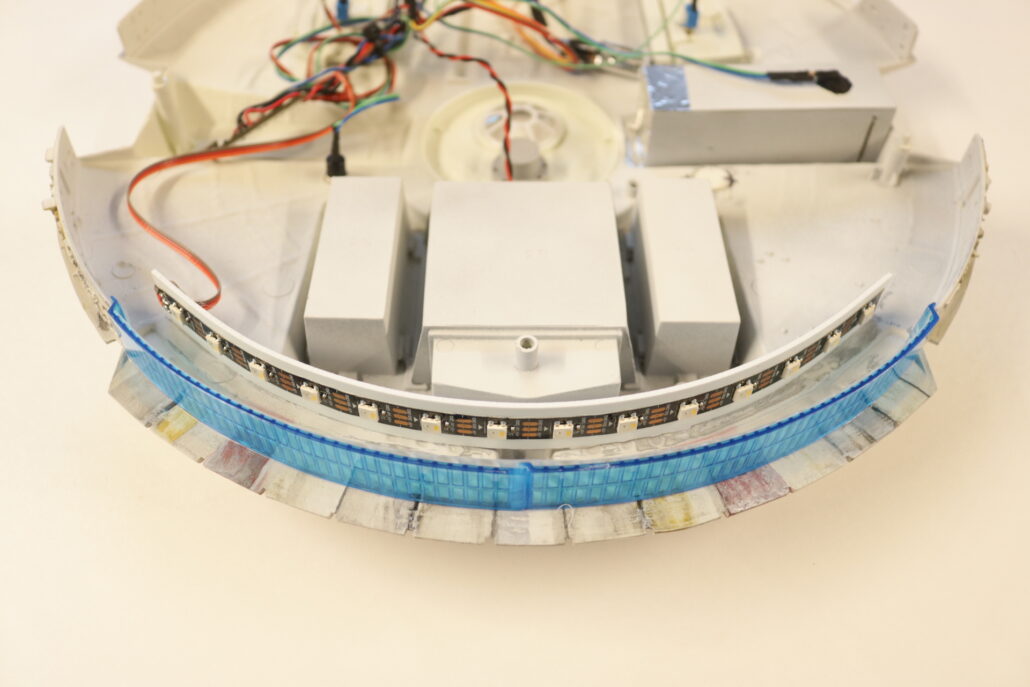
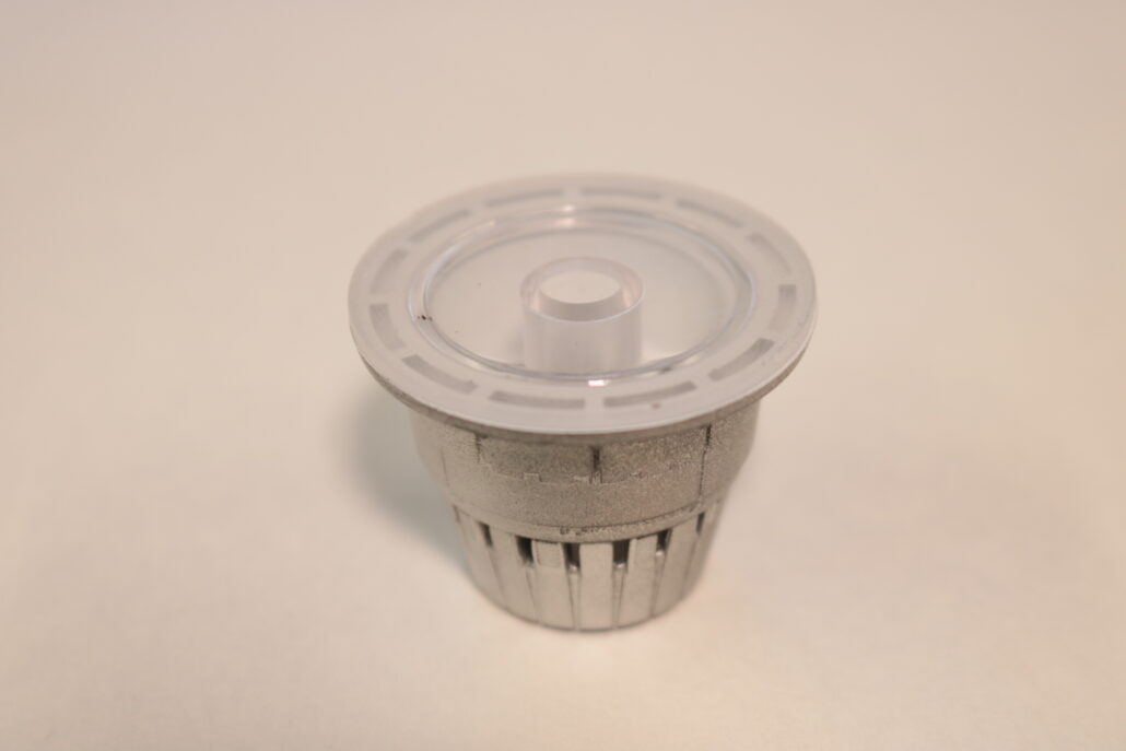
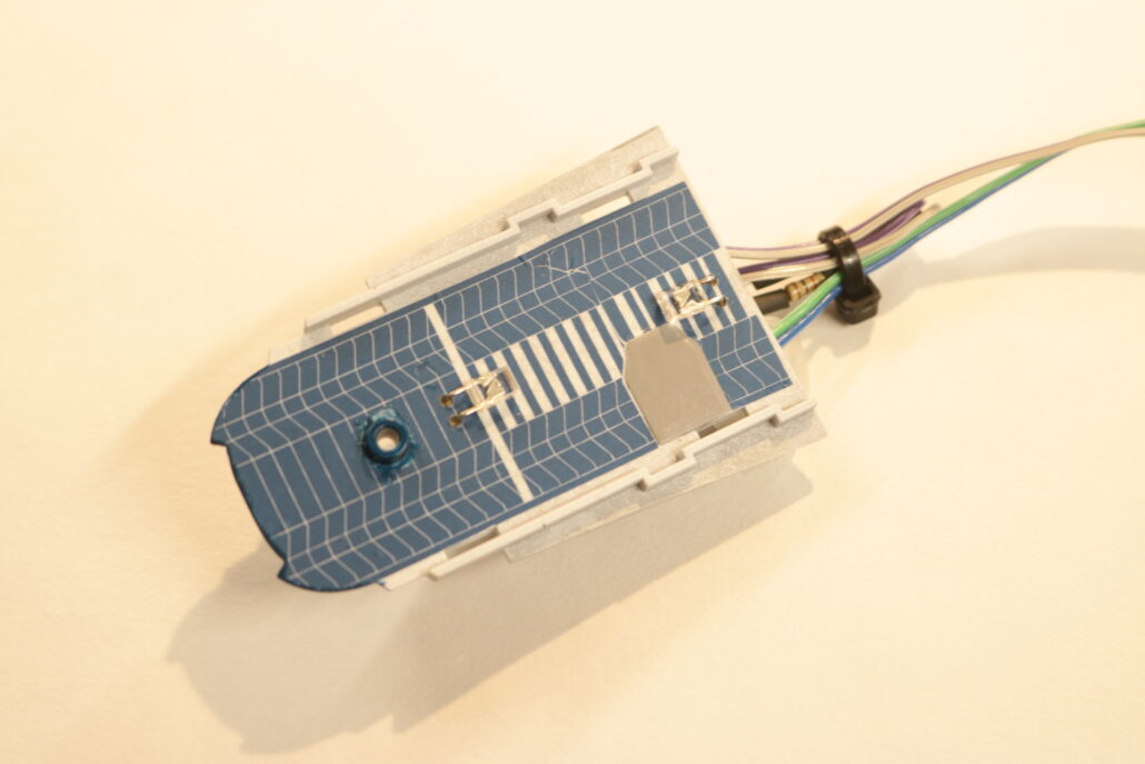
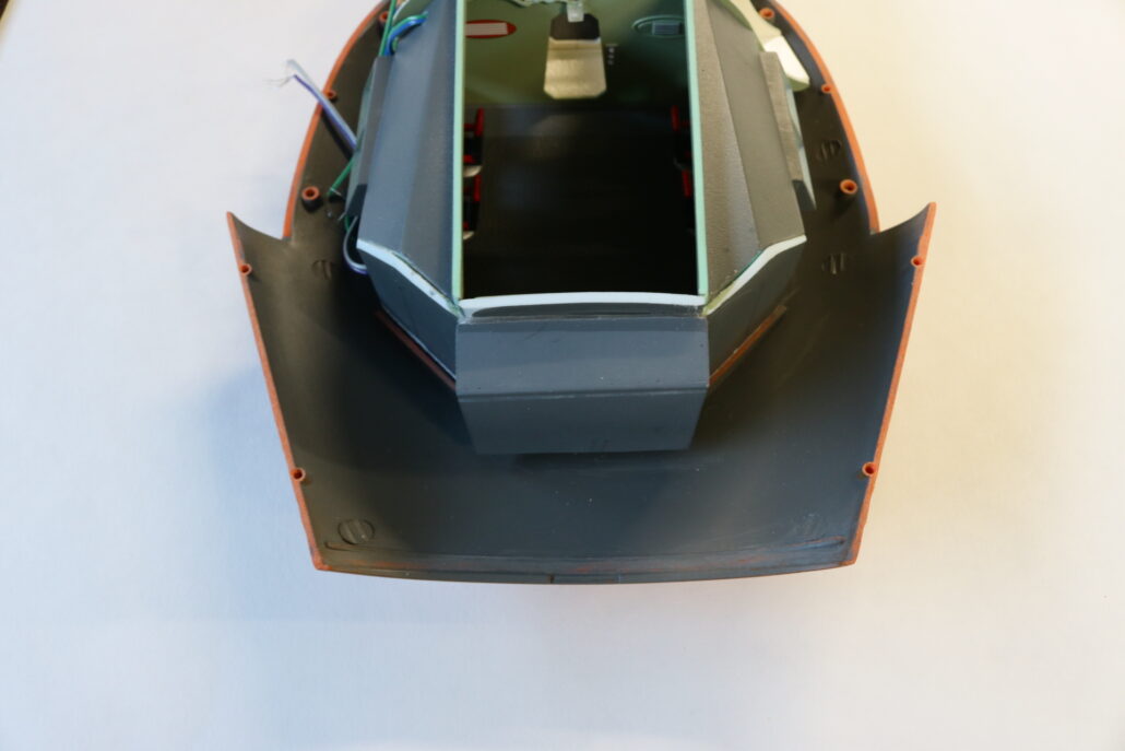
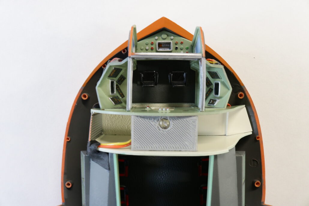
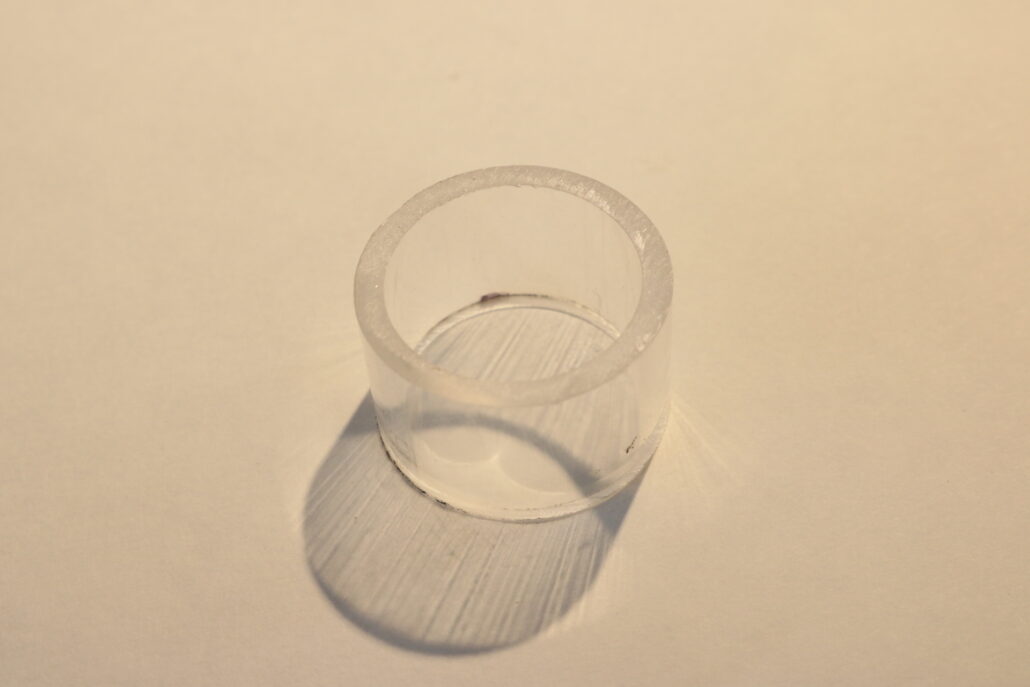
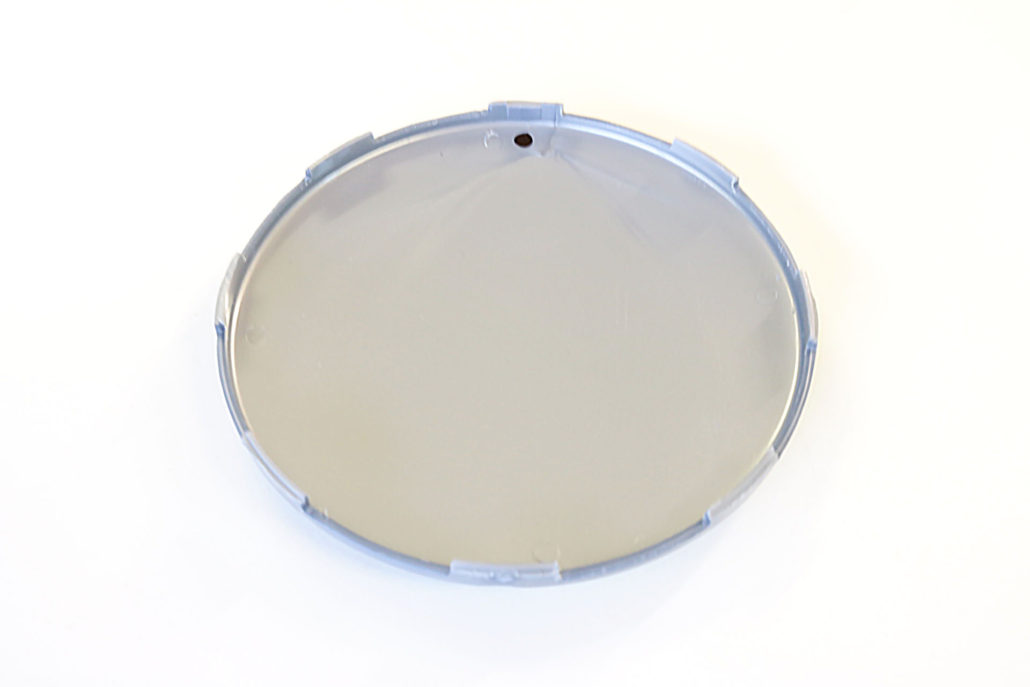
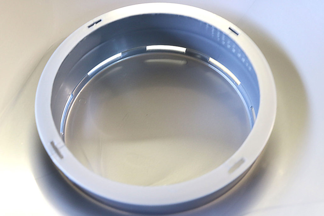
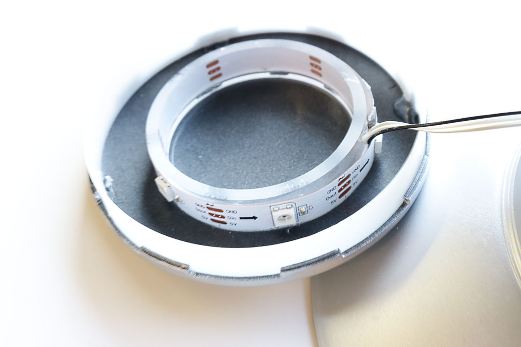
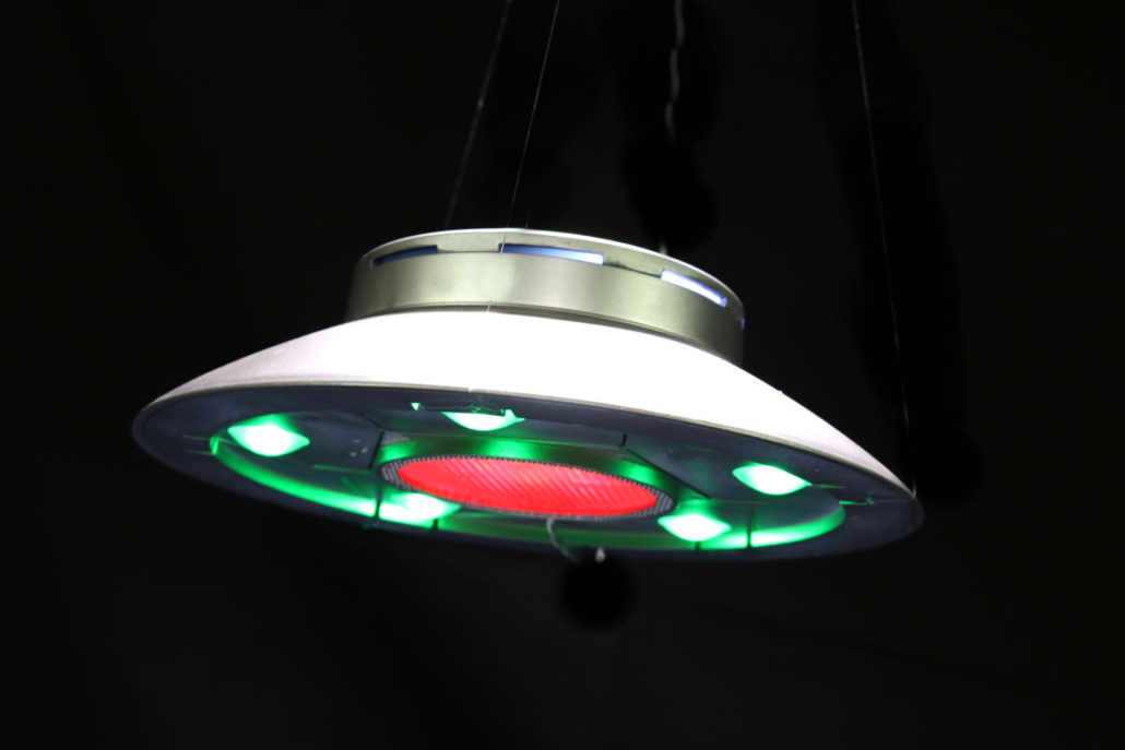
The top cover with the slot windows can be made using two different methods. Since the new kits comes with a clear top dome, the window slots can be masked off and painted. If using the clear part, make sure to mask of both sides of the slot window inside & out. If you’re using the standard top, you will need to remove the plastic around the window slot area. It’s very important to be very careful when removing this area around the window, as it is very easy to over cut the window frame. You will also need to install a 2 1/4″ piece of tubing in the center of the dome, to support the mounting of the slot strip. The kit also has a small piece of diffusion material that is mounted around the inside of the window slot. Cut to size and mount with a small amount of hot glue.
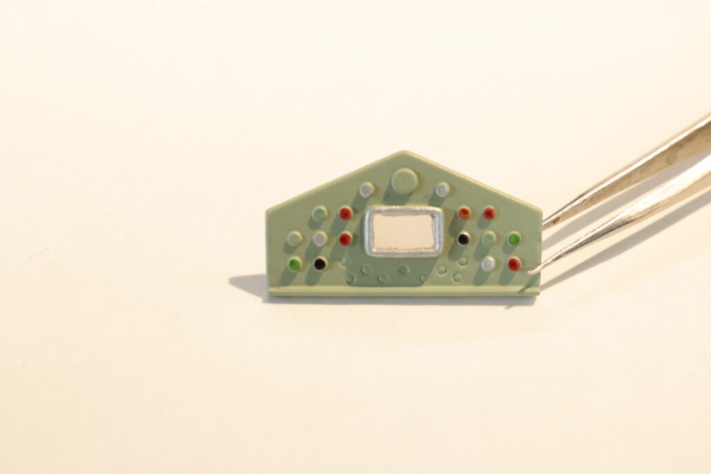
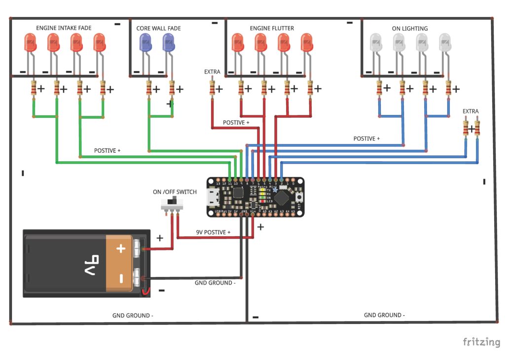
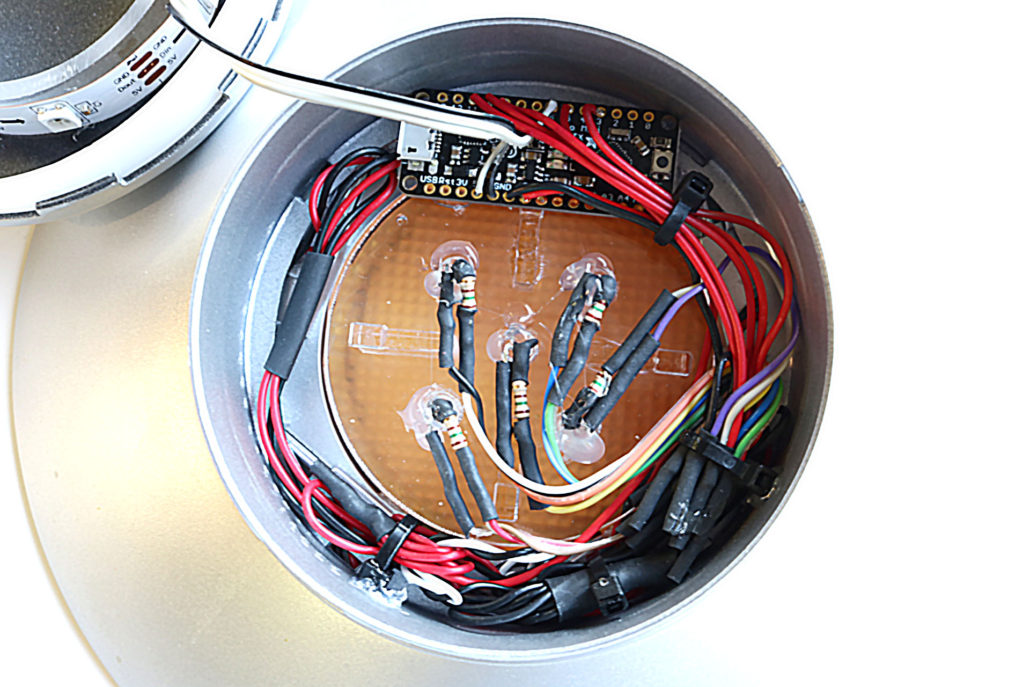
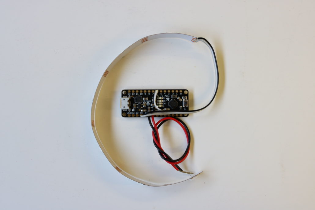
The circuit board hookup is next. The best way to get an understanding of the board is to study the wiring diagram. In a nutshell, the circuit board is based on series of pinouts, each pinout being a positive power pin that requires a inline resistor to protect the LED. In the diagram, the image shows only one LED, but it will support a maximum of ten LED’s for this project. Mode 1 is for “on lighting” only. Mode 2 is for all fading lights found in the engine, and mode 3 is for the strip or slot light effect. Mode 1-2 are intended for basic LED hook up, whereas mode 3 is based on one date wire for control. The strip is wired to pin 6, and goes directly to the strip marked “DATE”. Positive & negative power are connected to 5V positive & GND on the circuit board. “VIN” goes to the power source with GND direct, to the negative side of the main power source. If at any time you have trouble understanding the circuit board layout/assembly, please contact me directly.
Circuit board diagram
Once you have studied the circuit board, hook up an LED & test the pinouts for operation. At this point, you can also prefabricate the strip and wire it to the board. All other connection points for the LED’s can be soldered to the board when the top half of the model is glued in place. The final install of the circuit board will be tight, and will need to rest on the LED support bracket. The circuit board will need to lay flat, looking up towards the top dome. All the wires will need to be pushed down as close as possible to the LED bracket support. This will help prevent any wiring from hanging up on the top dome when it is set in place. Turn on power & test all locations for operation. Finally, you can use a small amount of white glue to mount the main upper dome part. This concludes the general instructions for the Invaders UFO lighting kit, if you have any questions please contact us directly at: