Millennium Falcon Lighting Kit
Getting Ready:
Unpacking the electronic parts kit, read all documentation & study diagrams.t is also good practice to have your own research material prepared before starting the lighting process. Start by reviewing all the model kit parts, get a general idea of how the model will come together. We will break down the model into two categories: on lighting – effects lighting. The main body comes in an upper & lower body half’s. When setting up for the electronics, you will need to build the lighting into the main body as a pseudo separate lighting system. The final result will be fewer wire connections as possible between the two main body parts & the rear engine assembly. Pre build, paint & mount leds as you move through the model construction, testing lighting as you go.
On Lighting:
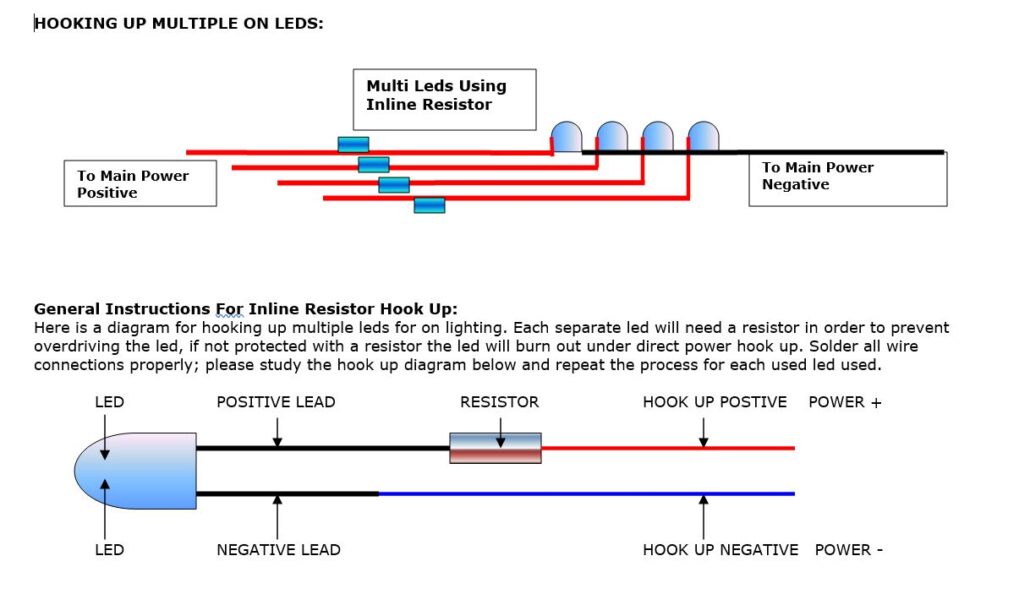
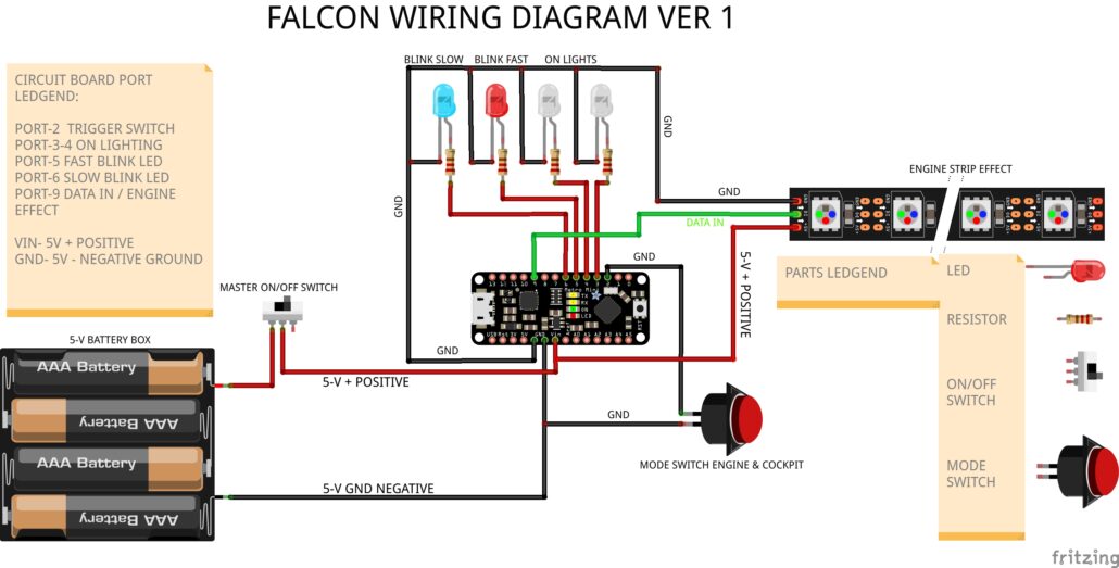
All the leds will use the in-line resistor set up, refer to diagrams above. When using this configuration, you have the choice of resistor to choose from to give different output levels for each led. Using the 220-Ohm resistor will give the brightest output within a safe operating range. Using the 1.5 K Ohm resistor will produce a dimmer output, giving you a much softer effect.
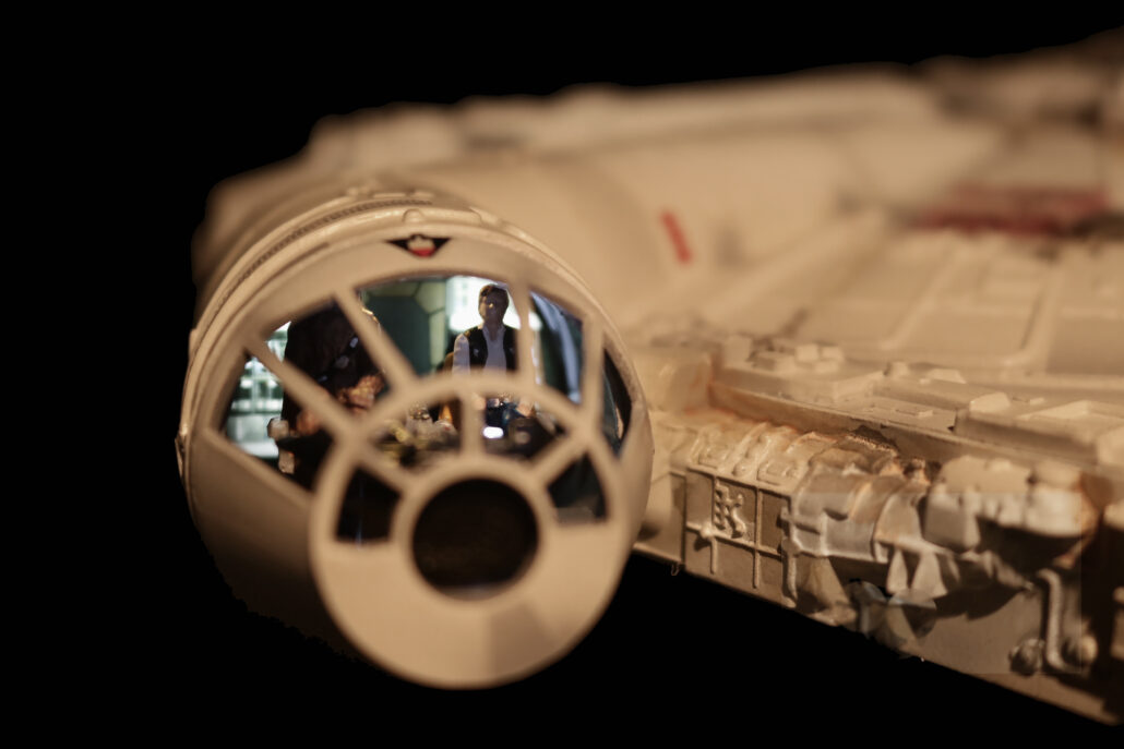
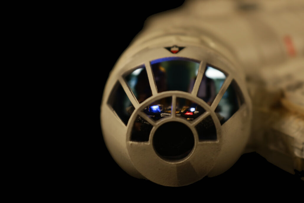
Cockpit Lighting:
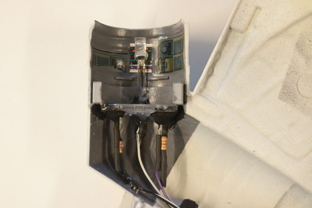
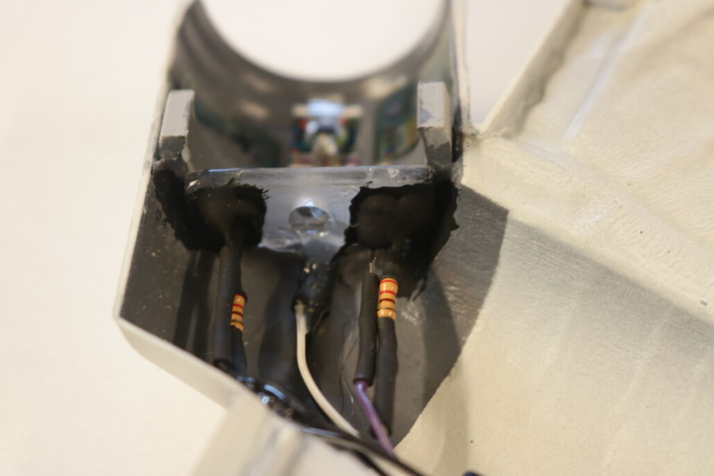
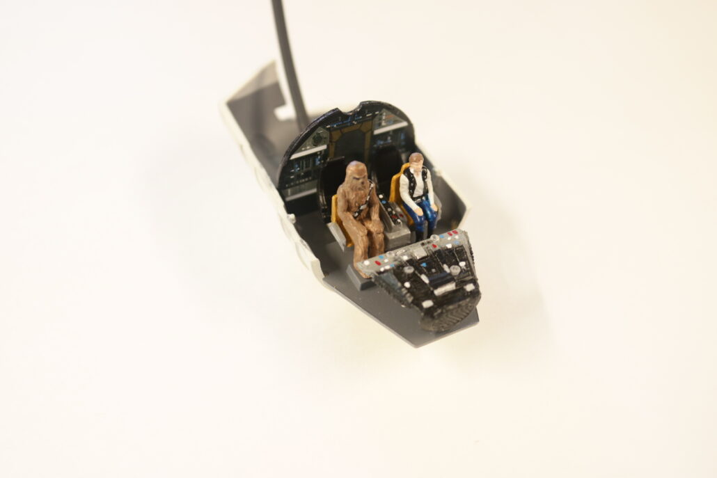
INTERIOR COCKPIT:
The interior cockpit area consists of a two white leds back lighting cockpit clear wall panel. You will be using the inline resistor system for each leds used. Tape off the backside of clear cockpit, apply decals as directed to the face side. Light block where need. Pre-built & paint where necessary.
Cockpit leds used: X-2 W 4.8mm wide leds mounted mid-way on each side of the clear back wall. Use 220-ohm resistors.
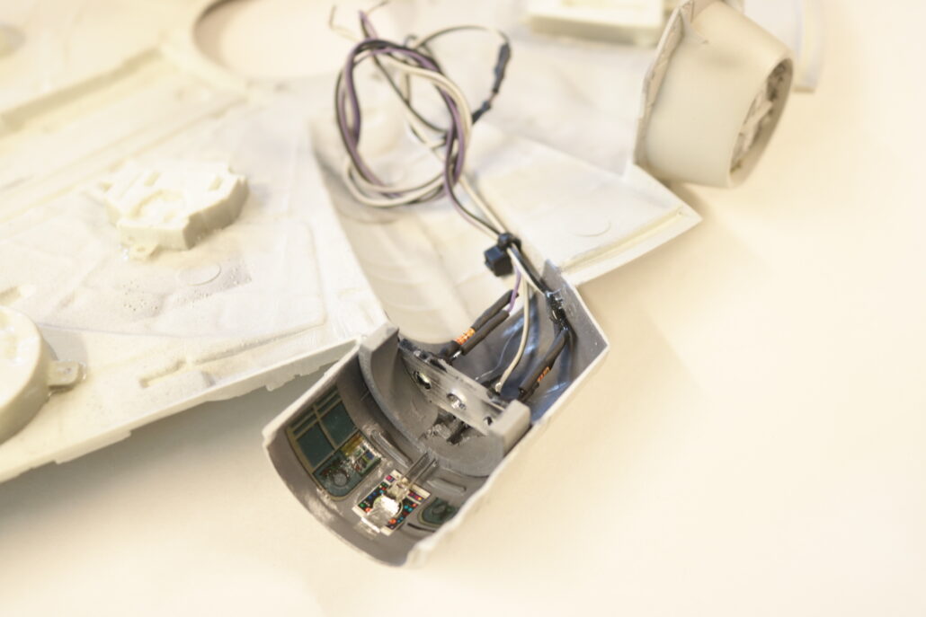
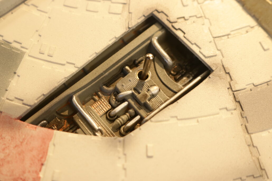
INTERIOR COCKPIT CONSOLE:
The interior cockpit area has a series of fiberoptic that can be used either on a scratch-built console or cockpit back wall. There are three zones, one is a fast blinker, one is a slow blinker & one is for on steady lighting. Use the inline resistor system to power each leds used. The kit comes with 9/32 tubing that will house these three lighting combos. The fiberoptic wires can be routed through the back wall or routed through the cockpit floor area.
Cockpit Leds used: X-1 R W5.0mm, X-1 B W5.0mm, X-1 W W5.0mm.
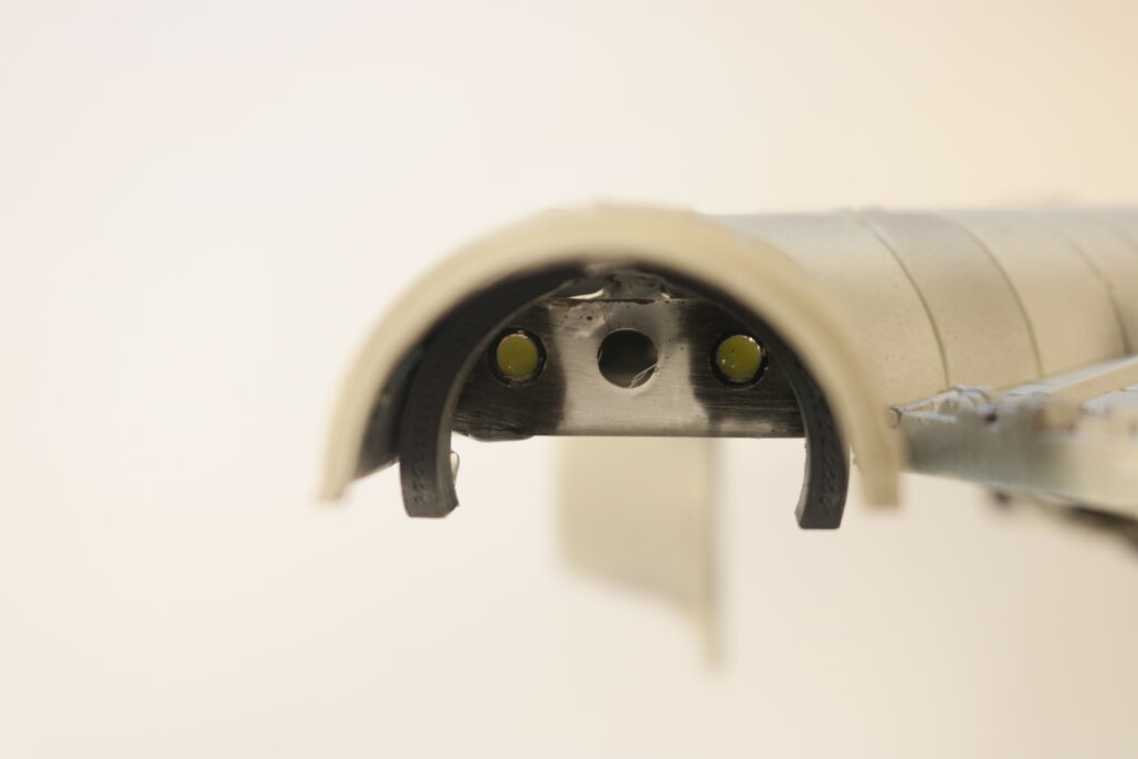

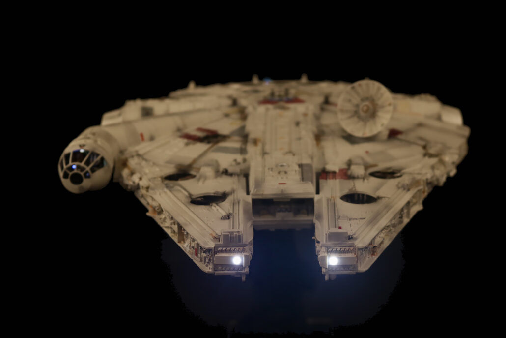
Head Lights:
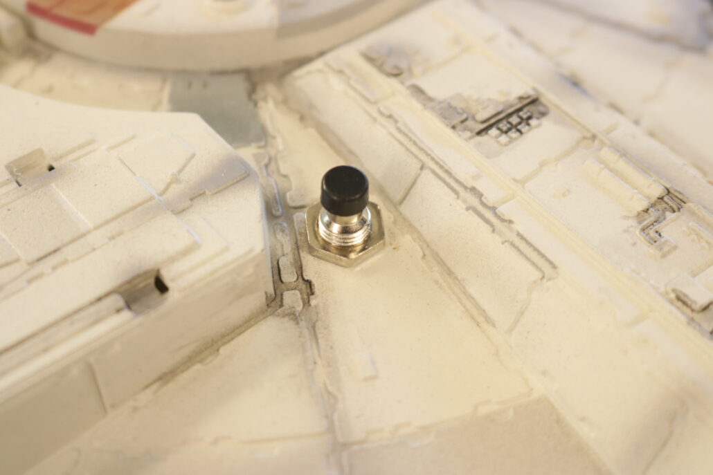
The main front headlights will need to be drilled out for two 3mm leds using the inline resistor set up to power each led used. Please study the wiring diagram. These are set up to have their own on/off switch controlled of the main power source after the main power cut off switch.
Head Lights Used: X-2 W 3.0mm. Use 220-ohm resistors.
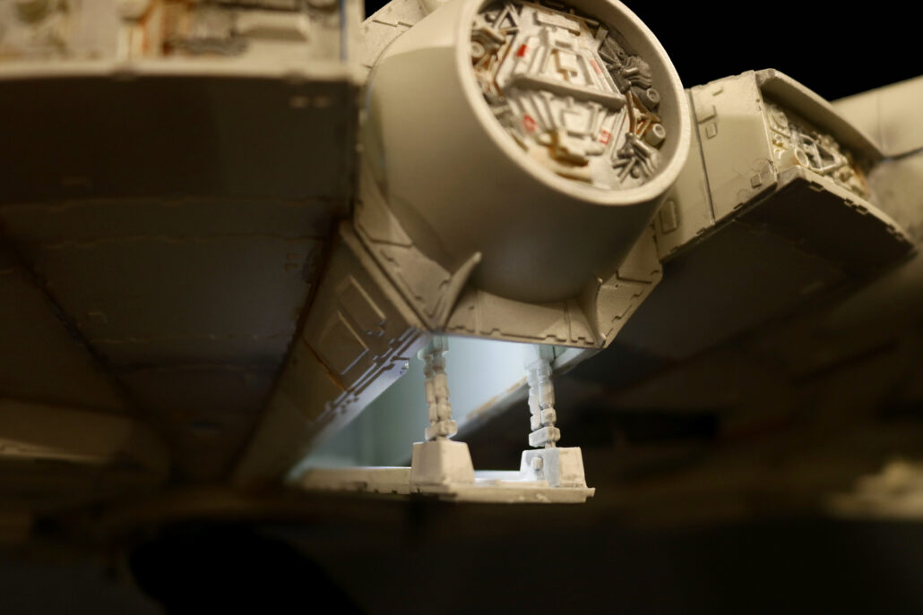
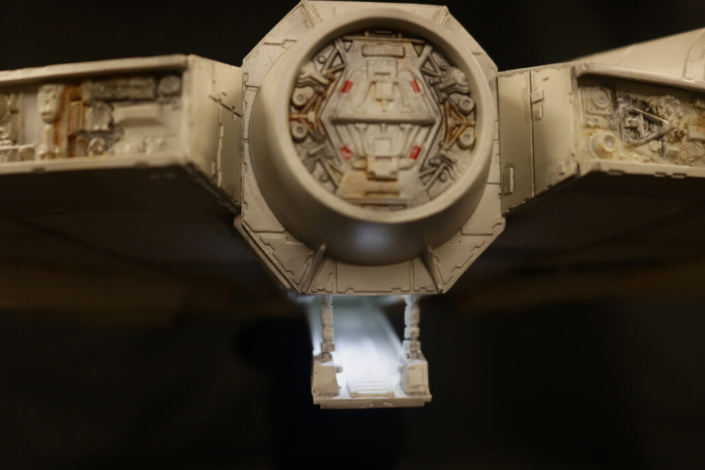
Passenger Ramp:
The passenger ramp consists of one led mounted in the mid upper roof area of the ramp looking downwards. You will be using the inline resistor system to power each led used. You might want to tie the headlights to the same on/off switch used for the passenger ramp.
Passenger Ramp leds used: X-1 W 3.0mm. Use 1.5K-ohm resistors.
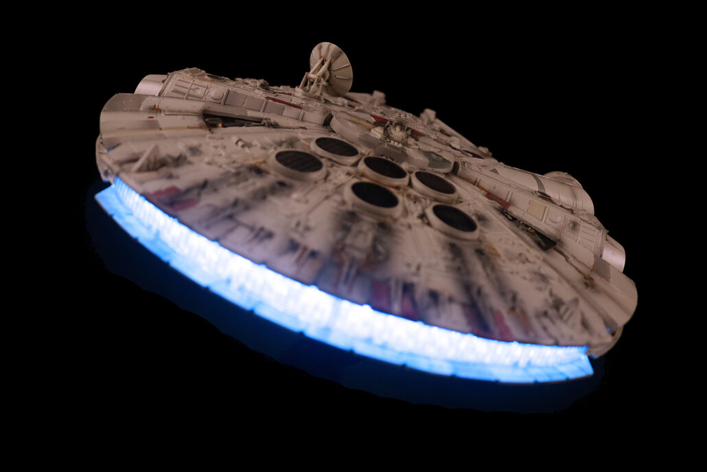
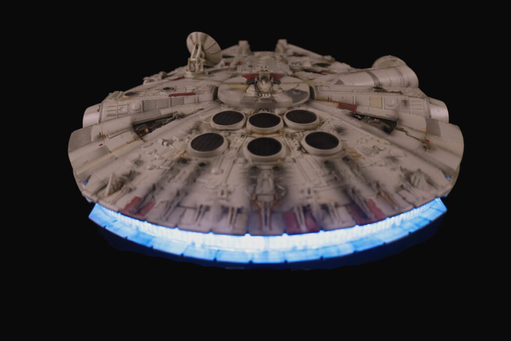
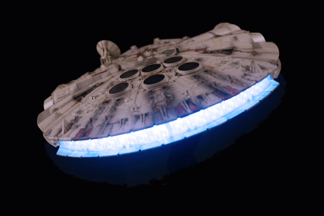
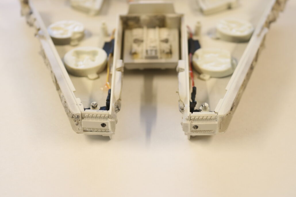
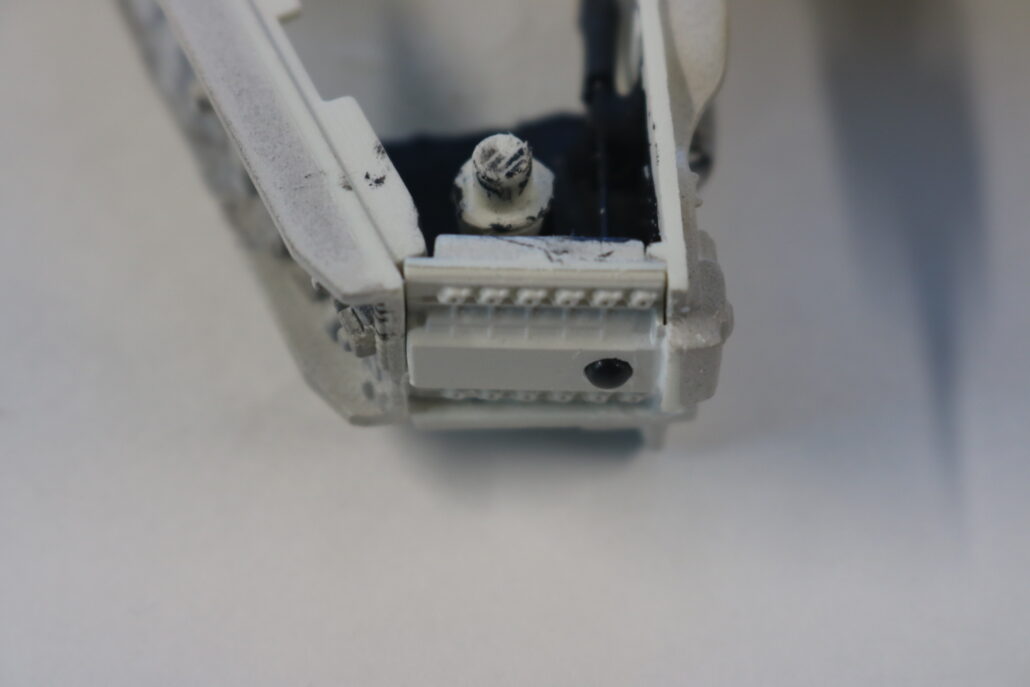
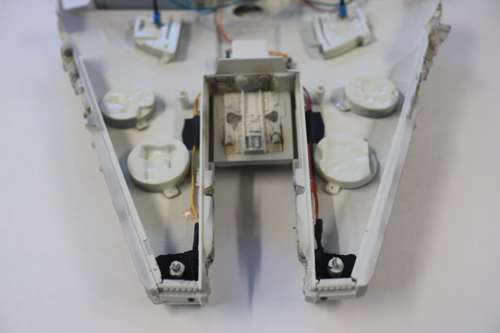
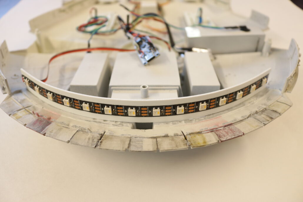
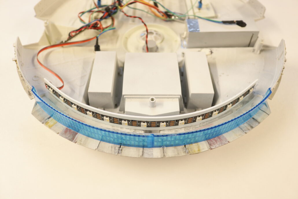
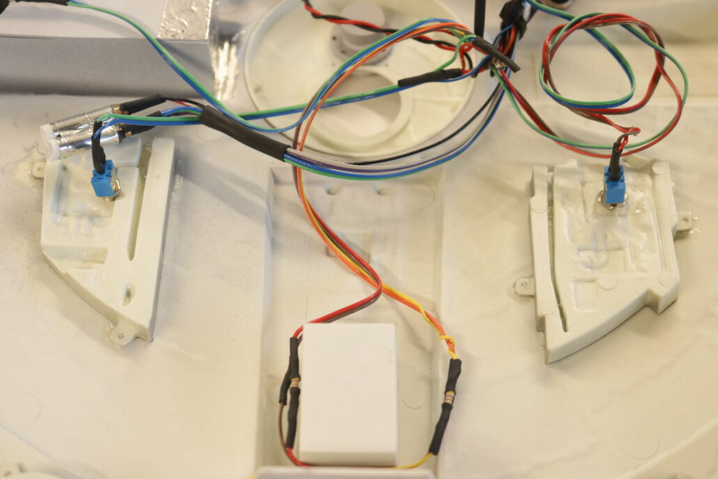
Engine Effect:
The engine used a RGBW strip to power the engine feature. You will need to construct a strip of styrene bent to the angle of the engine curve. The kit also comes with a diffusion material that will need to be cut to fit against the clear blue stock lens. The led strip has three pads, 5V+, 5V-, DATA IN. Data in will be hook up for port 9 on the controller board. There is also a switch port that will turn on the engine effect and cockpit lighting. Port 2 on the controller board controls the advancement of the effect. It is very important that you pay attention to the arrow on the strip that is flowing away from the fist point of contact. No inline resistor is required for the strip & you can driver the main 5V + direct from the power source after the main on/off cut off switch.

Wiring Diagram:
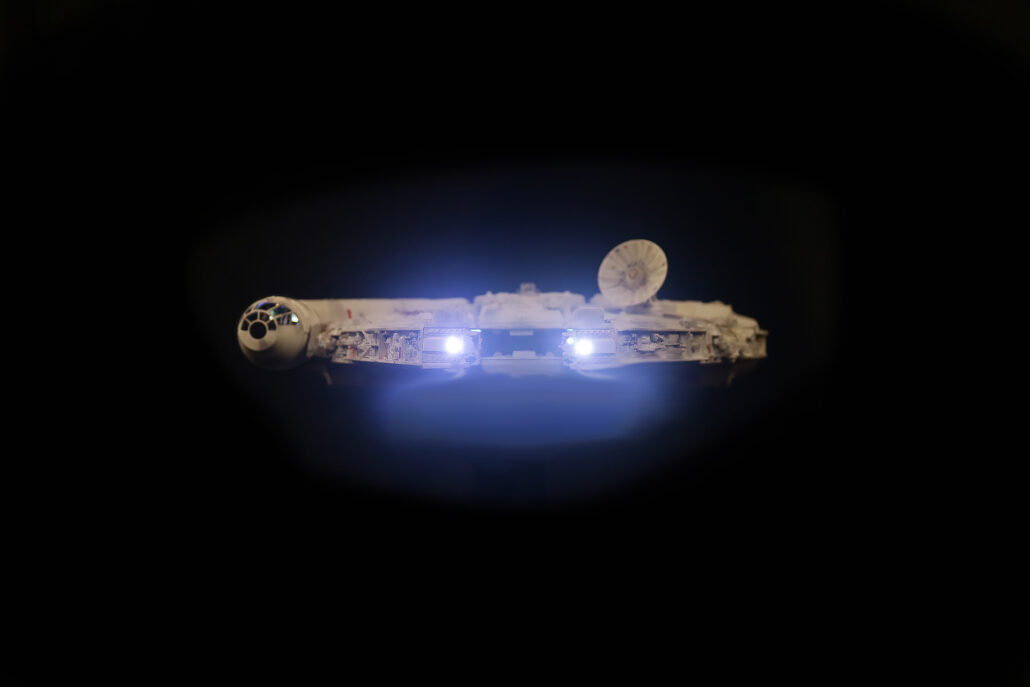
Finished Photos: