Tie Fighter Lighting Kit
Getting Ready:
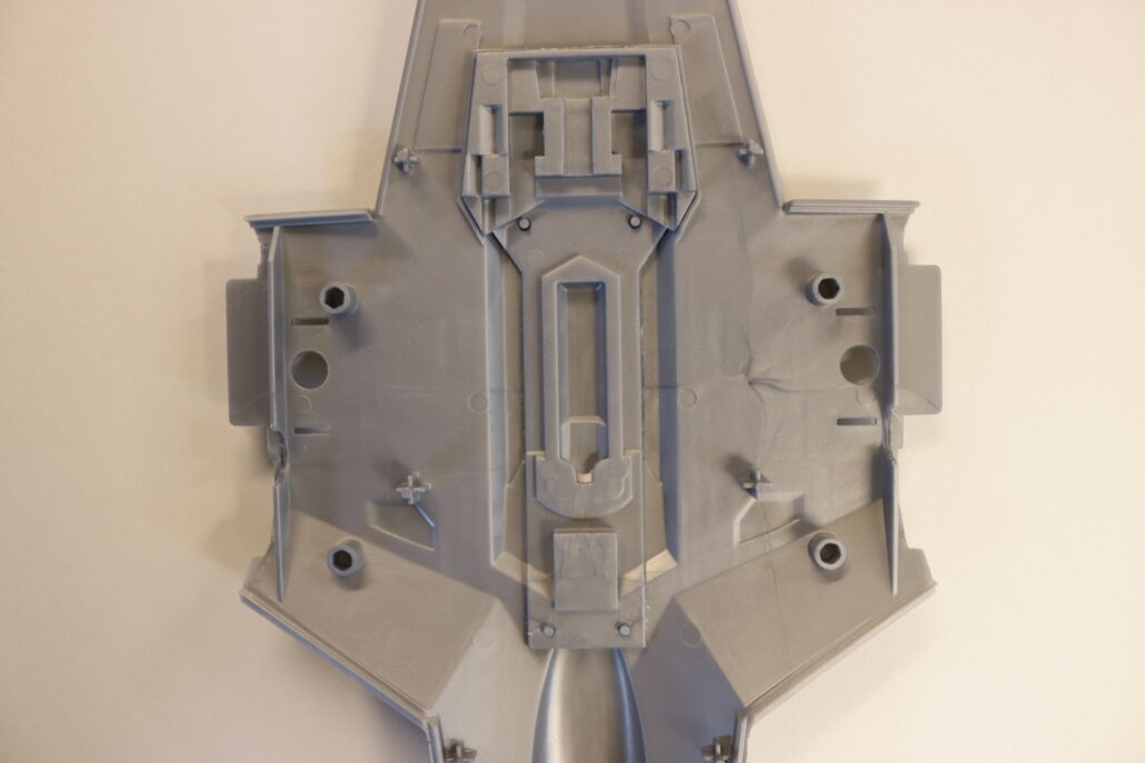
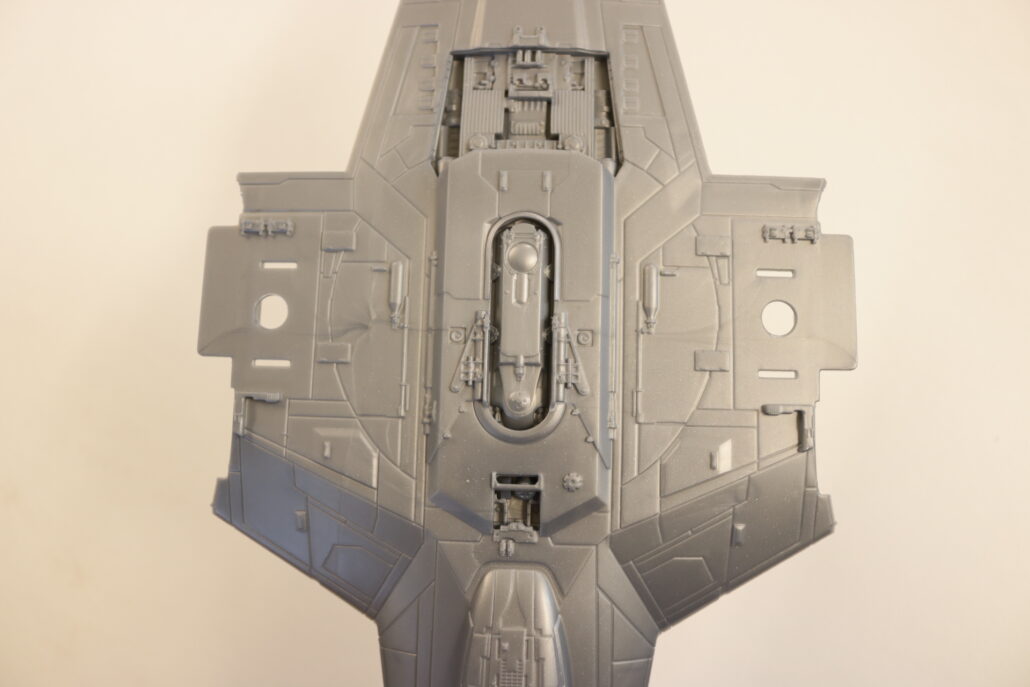
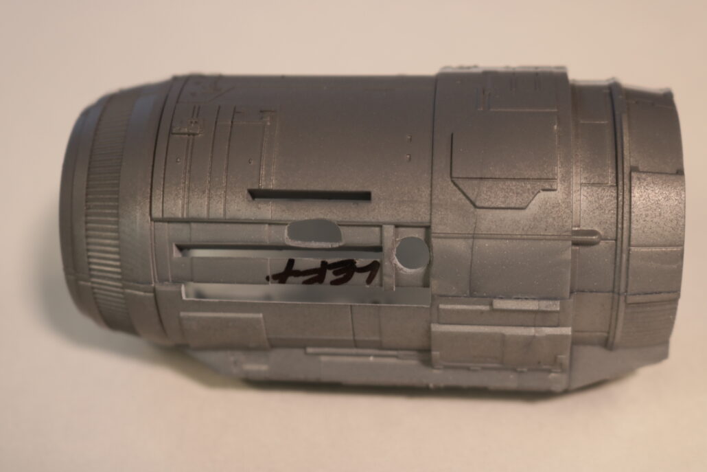
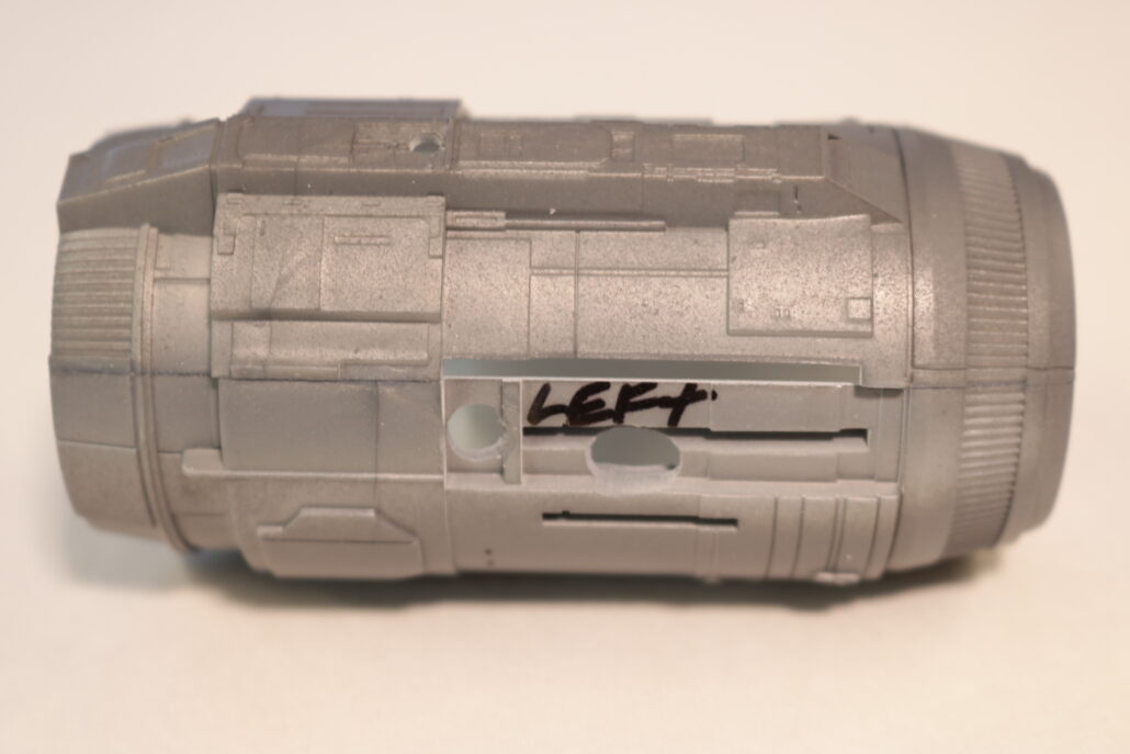
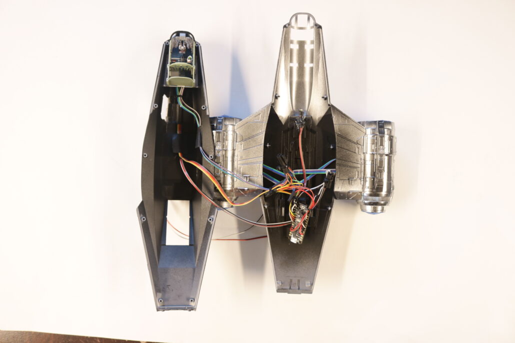
Unpacking the electronic parts kit, read all documentation & study diagrams. It is also good practice to have your own research material prepared before starting the lighting process. Start by reviewing all the model kit parts, get a general idea of how the model will come together. We will break down the model into two categories: on lighting – effects lighting. The main body comes in an front & rear body half’s. When setting up for the electronics, you will need to build the lighting into the rear half of the body after the main interior cockpit is inplace. The final result will be fewer wire connections as possible between the front & the rear half’s of the body. Pre build, paint & mount leds as you move through the model construction, testing lighting as you go
On Lighting:
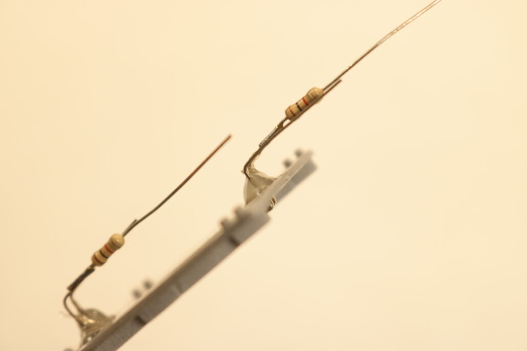
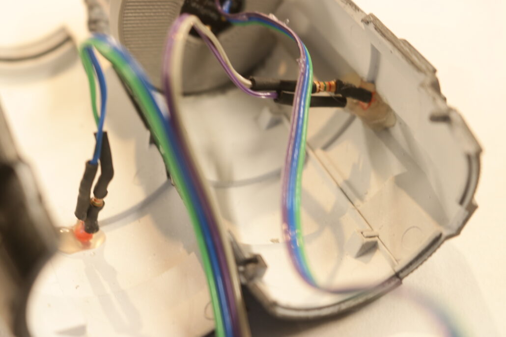
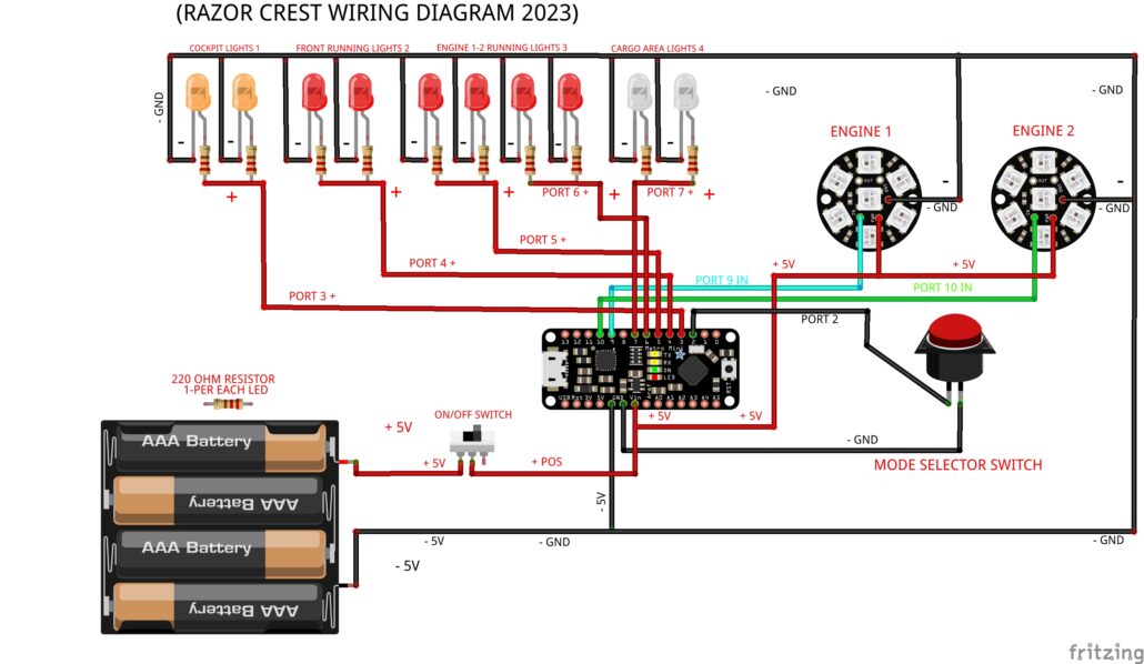
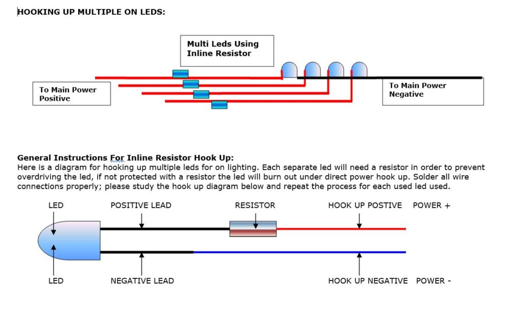
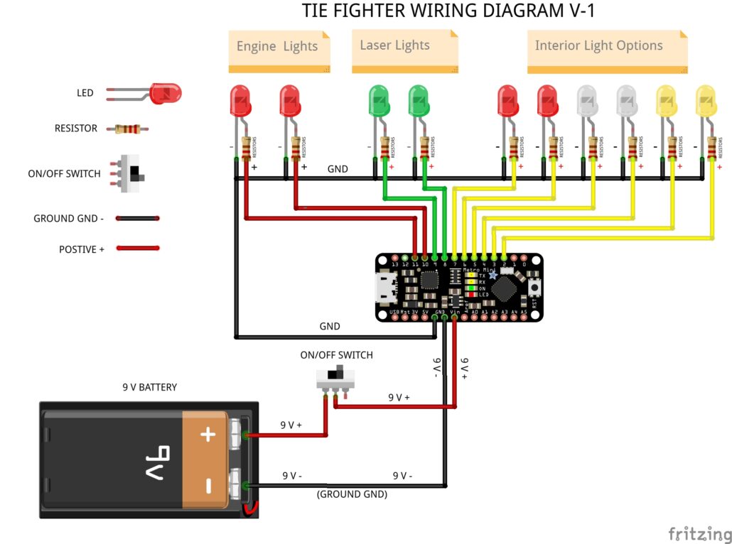
All the leds will use the in-line resistor set up, refer to the diagrams. When using this configuration, you have the choice of resistor to choose from to give different output levels for each led. Using the 220-Ohm resistor will give the brightest output within a safe operating range. Using the 1.5 K Ohm resistor will produce a dimmer output, giving you a much softer effect.
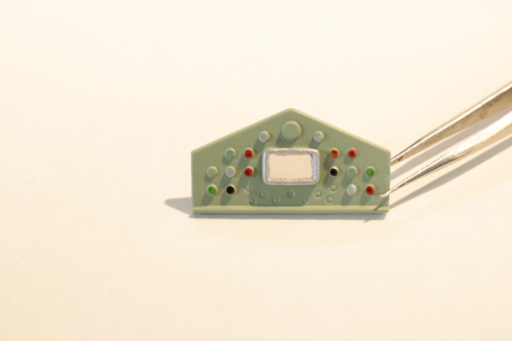
Circuit Board:
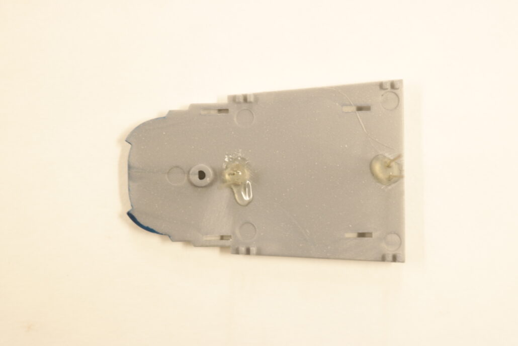
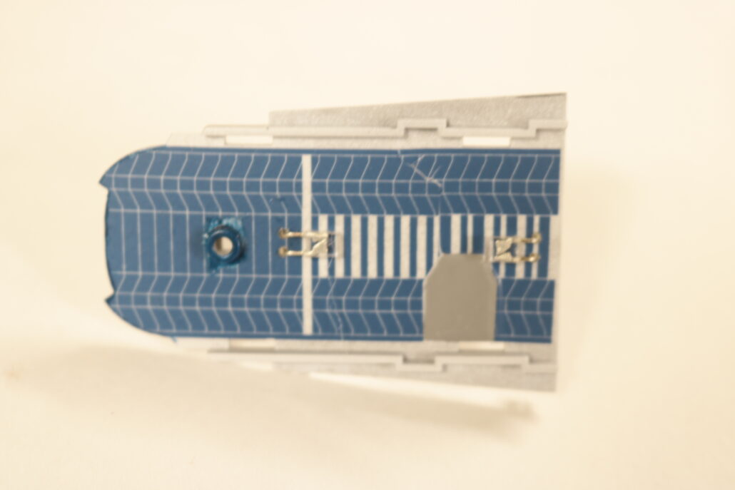
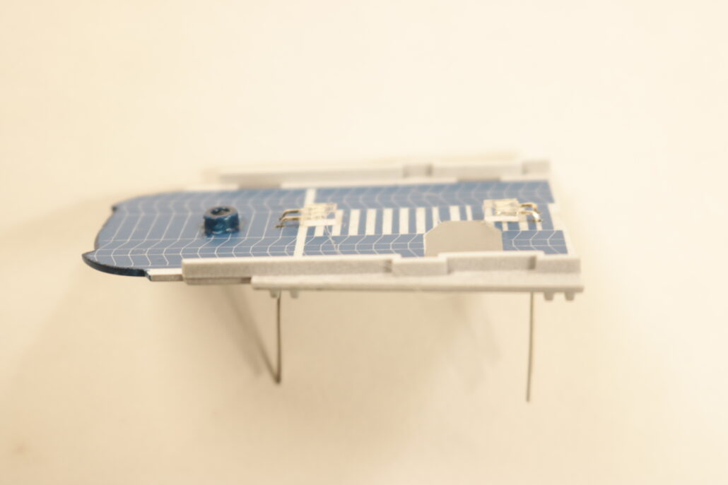
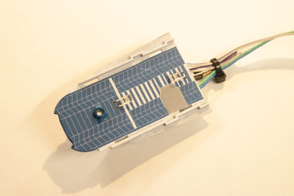
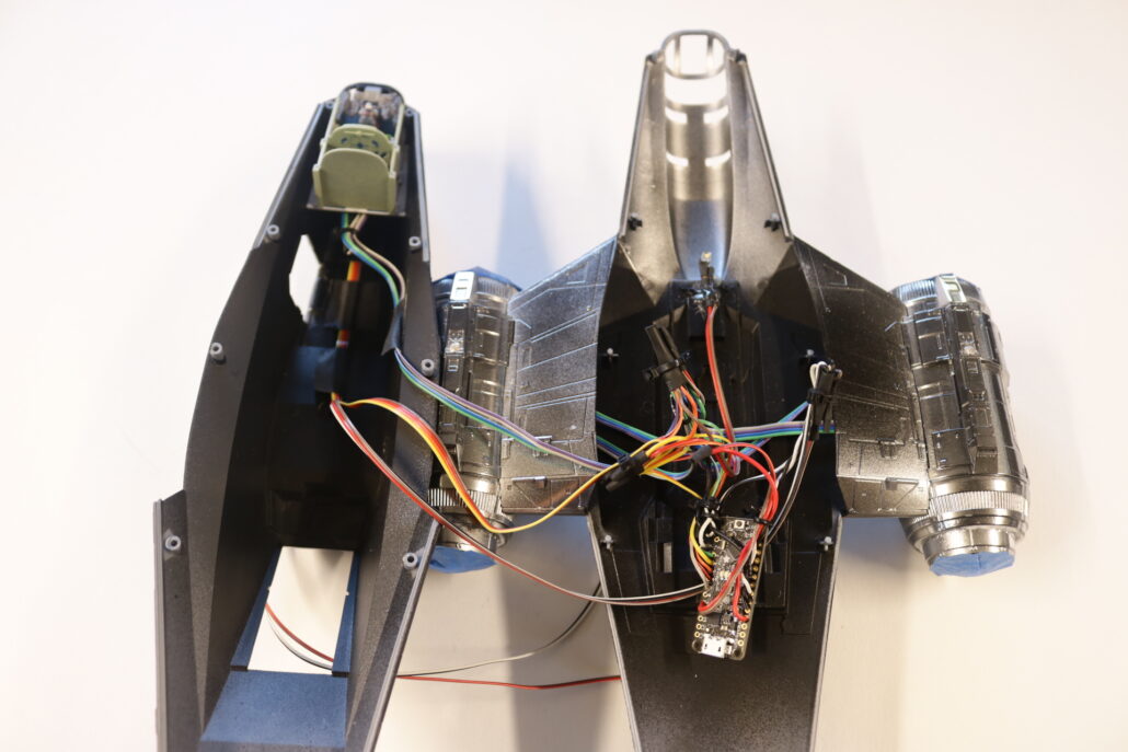
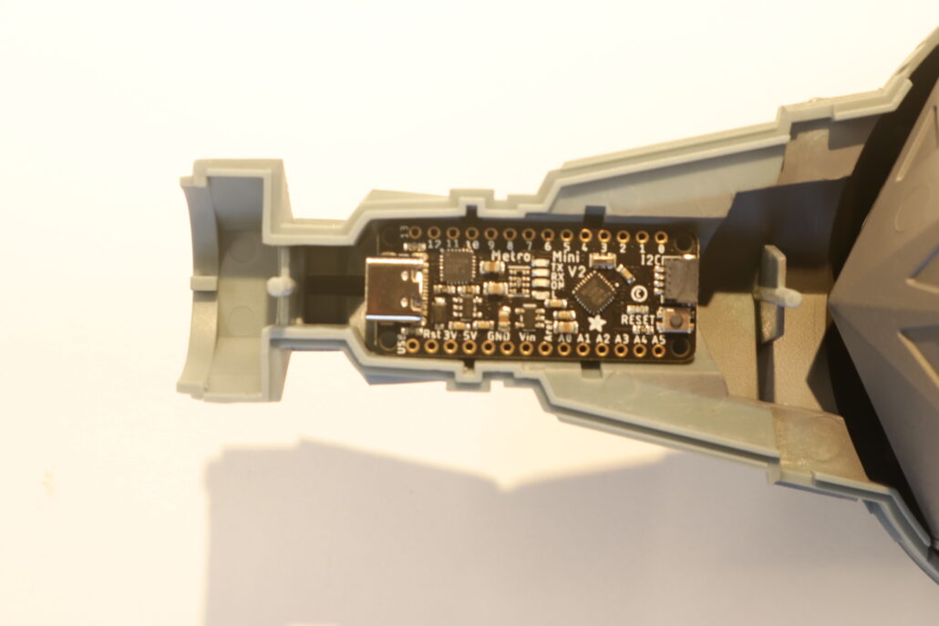
The main circuit board used to run all the lighting effect will need to be mounted in a wing strut cavity. This is the only space that you can mount the board with in the model, either side can be used & for those that want to access the USB C Port you will need to remove the end mounting pin & leave the wing cover accessible for hook up to the USB Port.
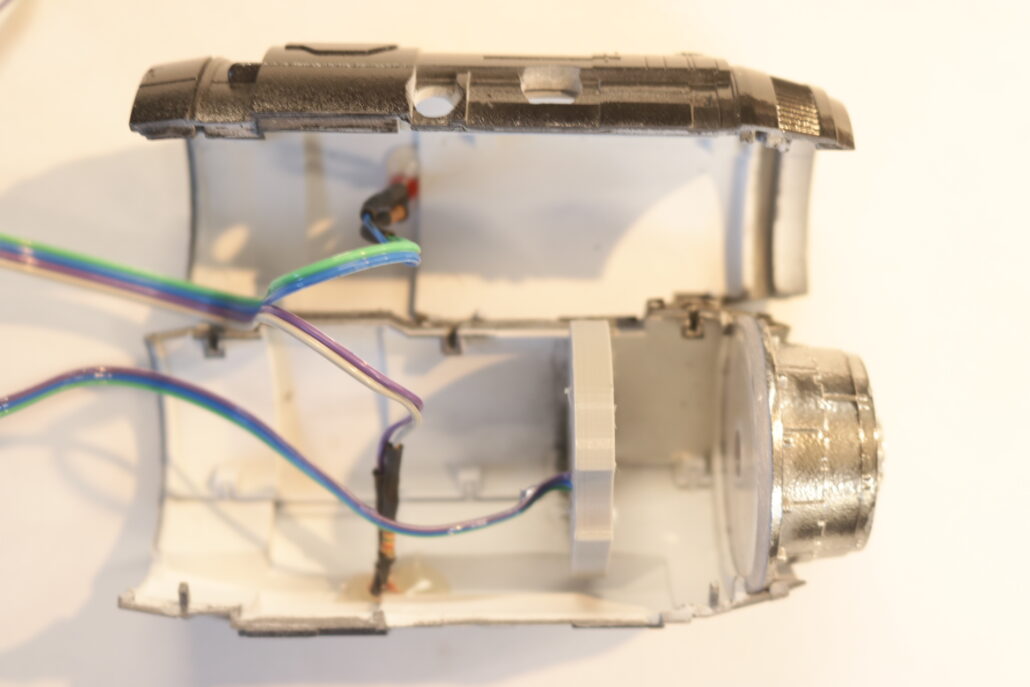
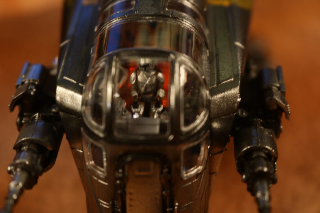
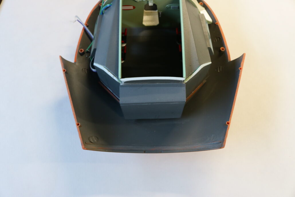
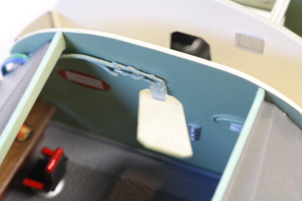
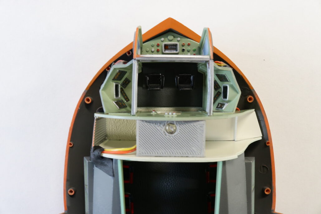
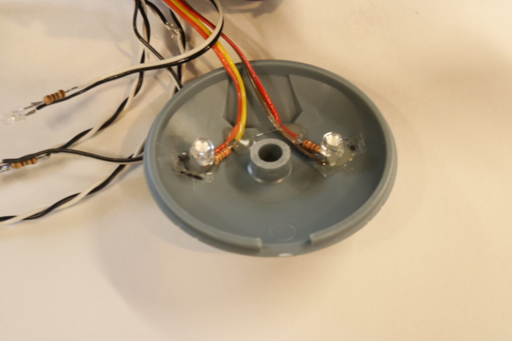
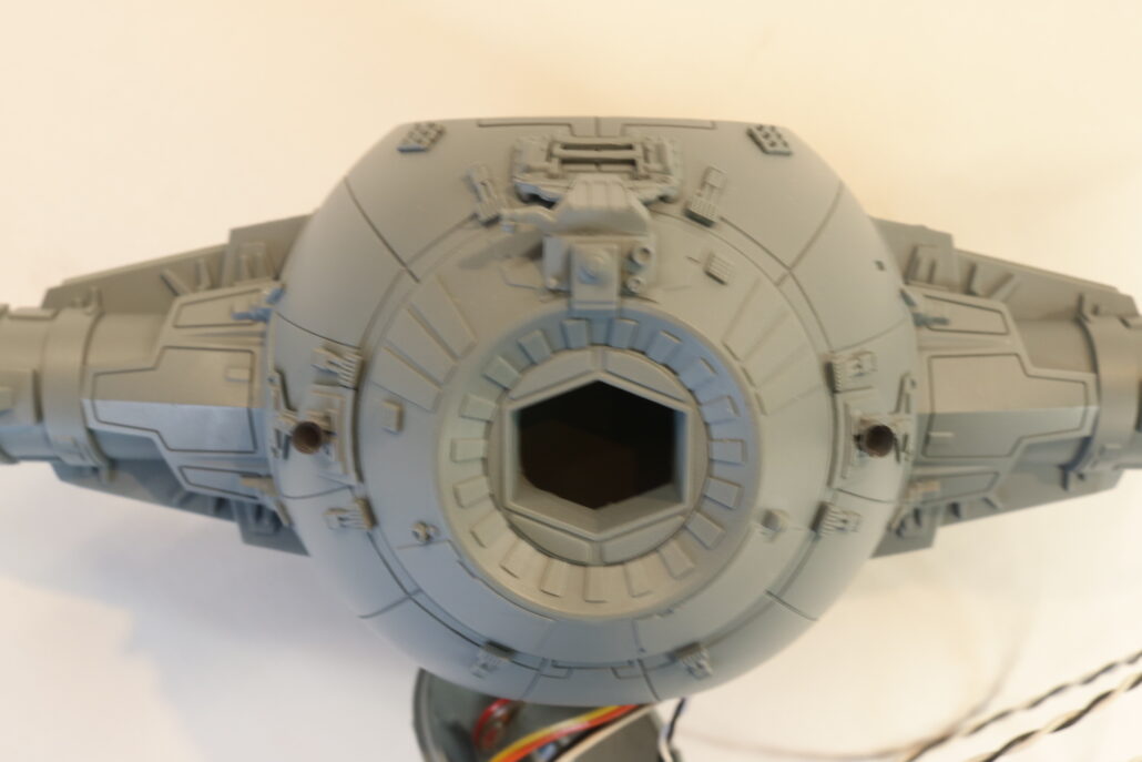
Cockpit Lighting:
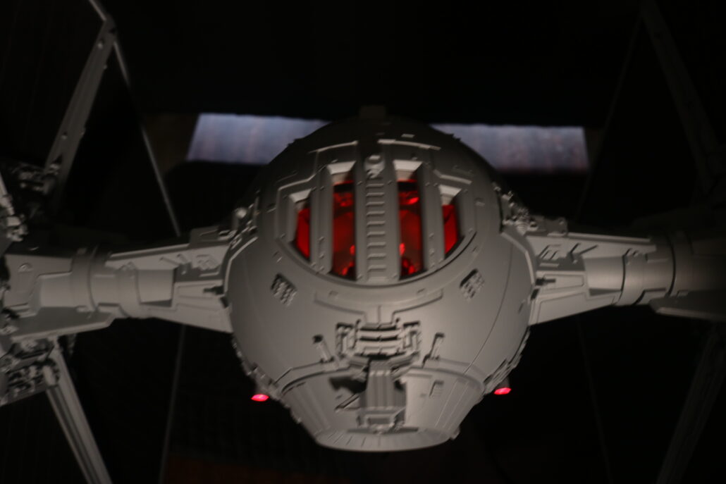
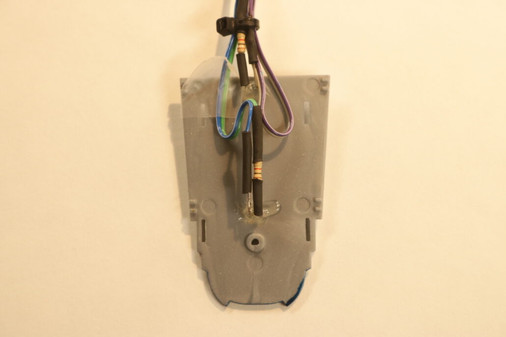
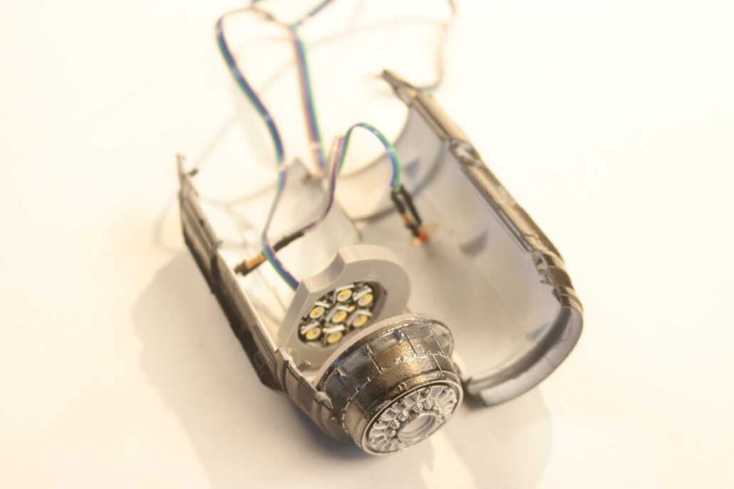
The interior cockpit area consists of a two red leds mounted in the very bottom of the mounting rod area. The two red lights are mounted on either side of pilots seat, looking upwards through the clear floor part. You will be using the inline resistor system for each leds used. Light block where need. Pre-built & paint where necessary.
Cockpit leds used are X-2 R 4.8mm wide leds mounted in the bottom of the mounting rod aera. Use 220-ohm resistors & connect to circuit board ports 2-7
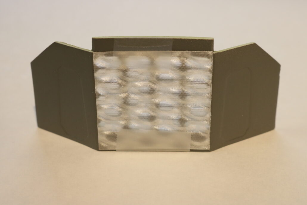
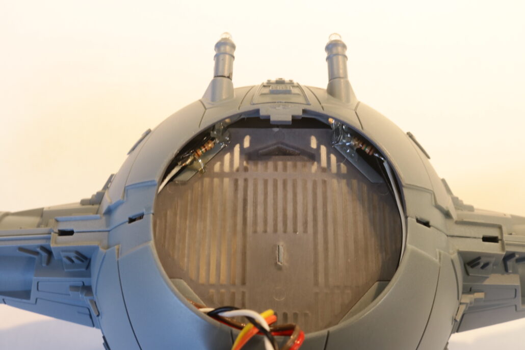
Lasers Cannons:
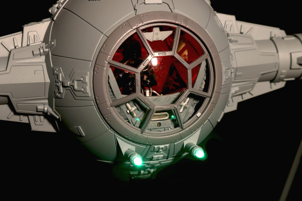
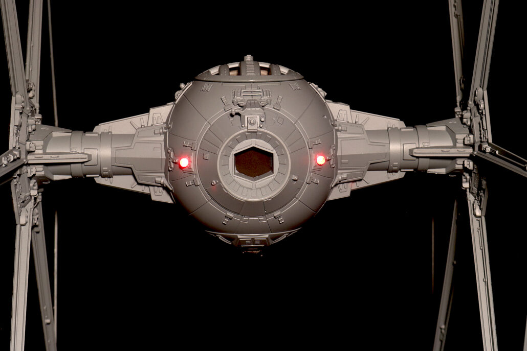
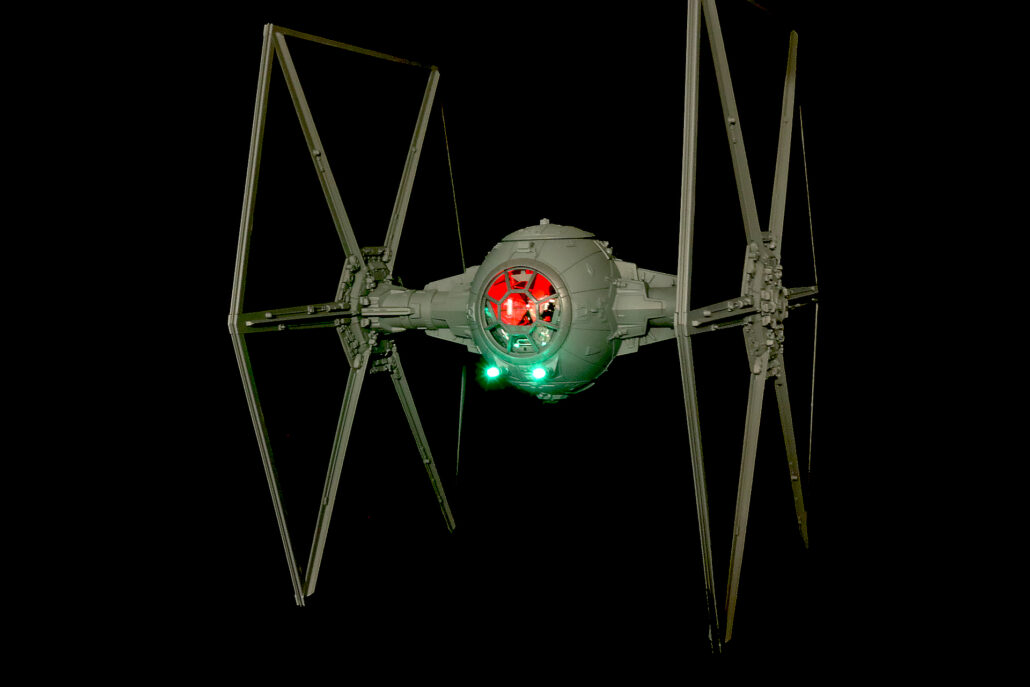
On the front of the ship there are 2 clear laser cannons in clear. These clear parts will need to be taped off or protected on the end tips & the very back where the leds will but against the back of the clear part transfering the light to the end of the tips. Use the X-2 green leds with the 150-ohm in line resistors set up. Connect to circuit board ports 8-9 fro laser cannon effect. You will need to slightly bend the leds & wire’s closer to wing strut so they are not seen by the red floor lights.
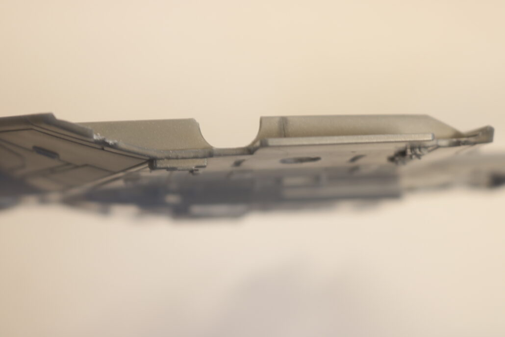
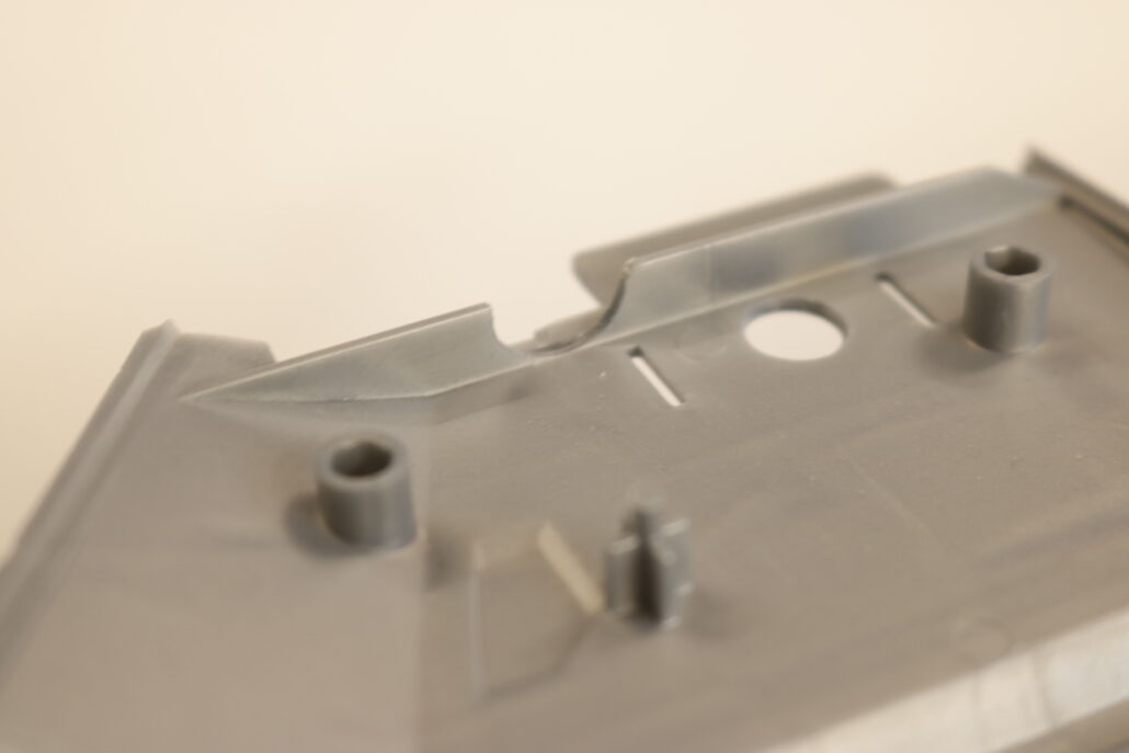
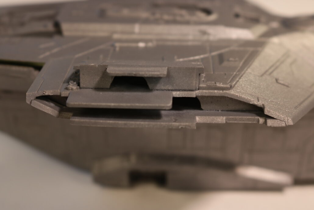
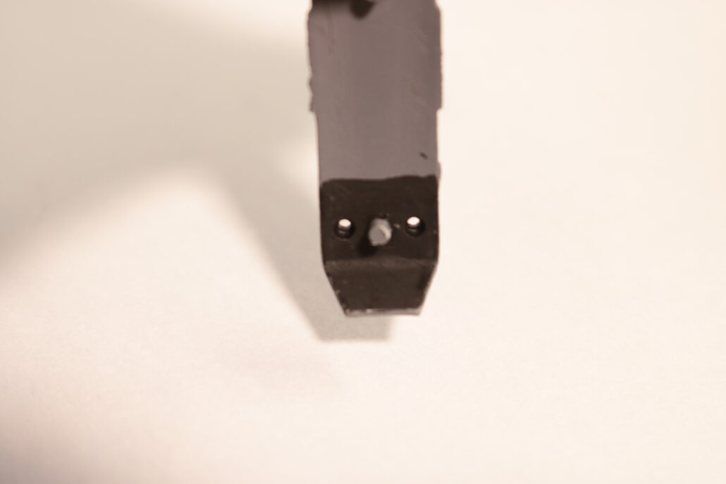
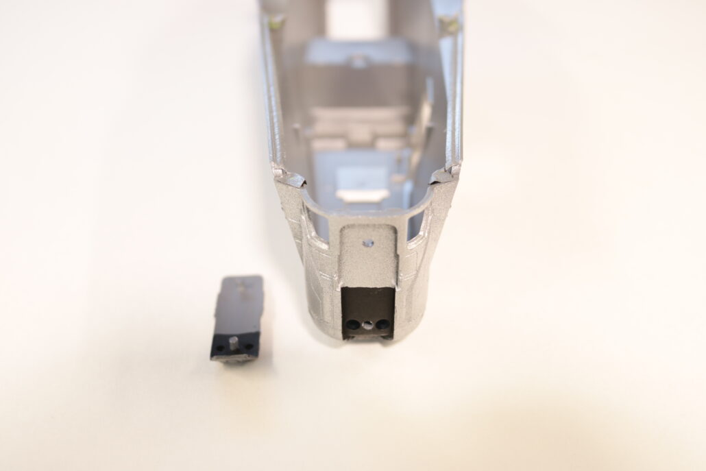
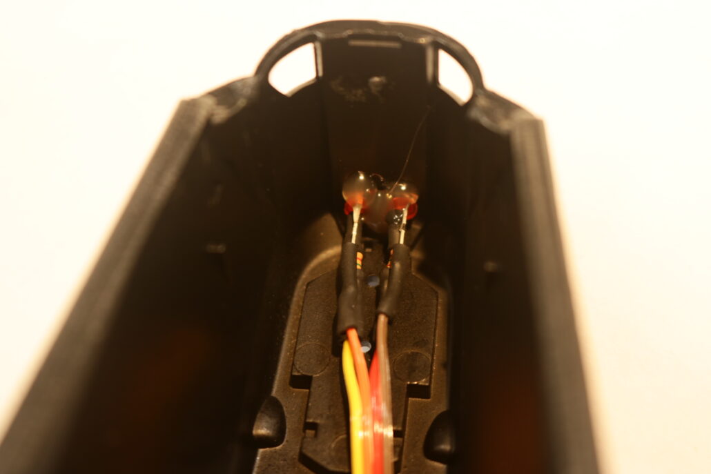
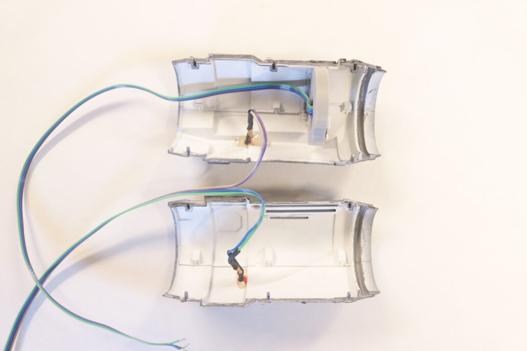
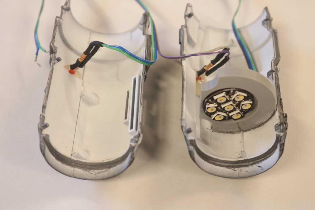
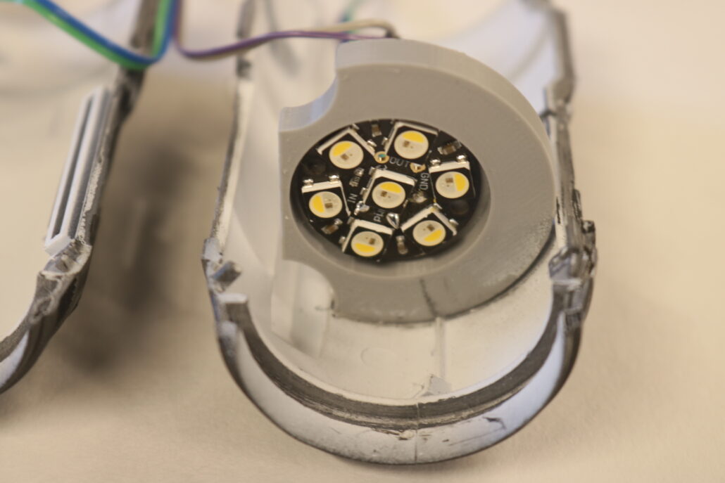
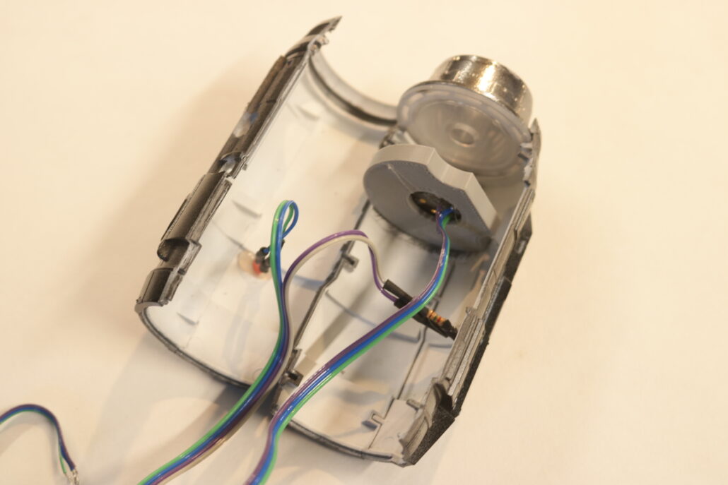
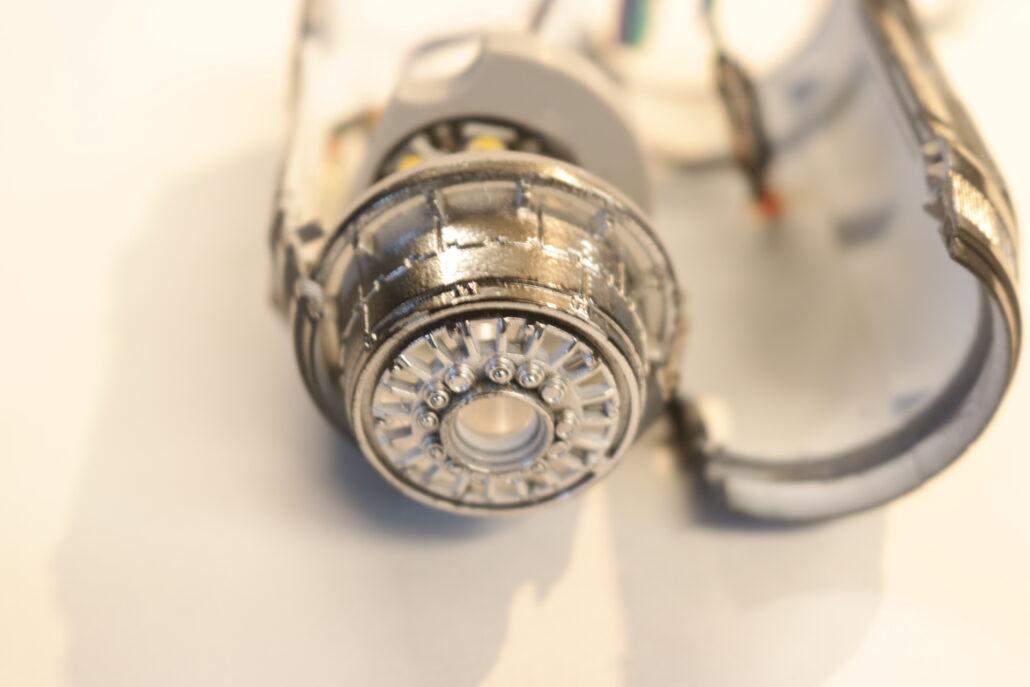
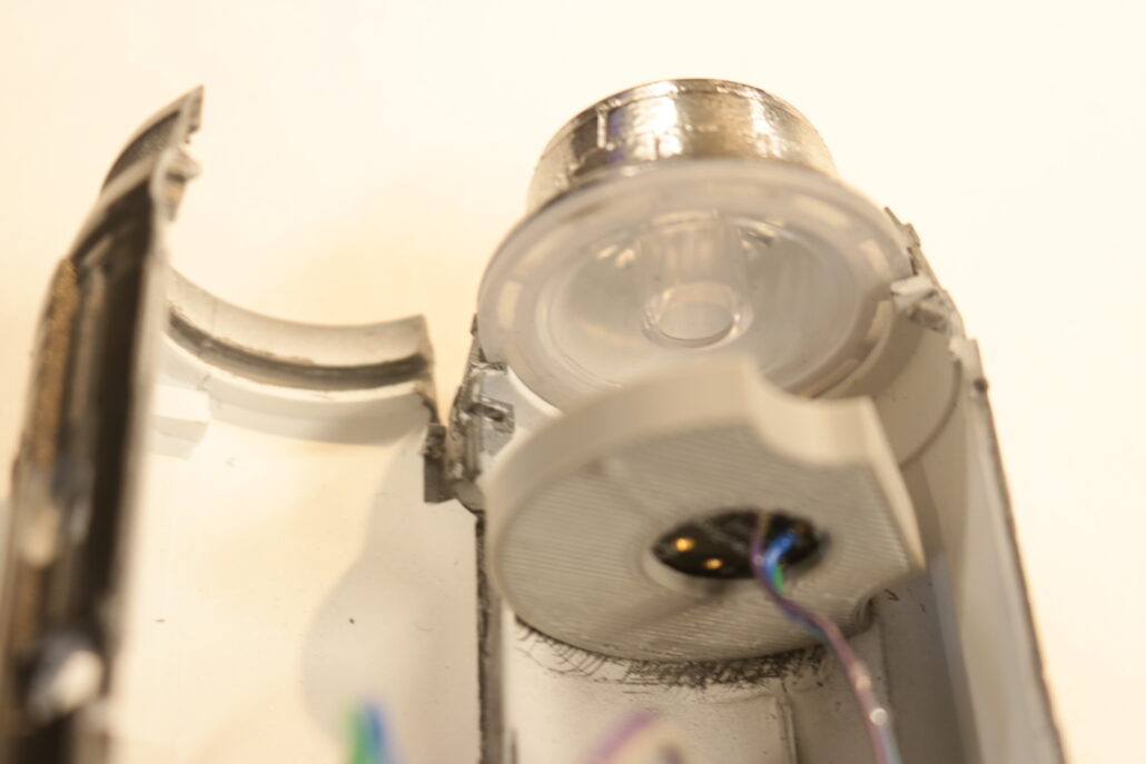
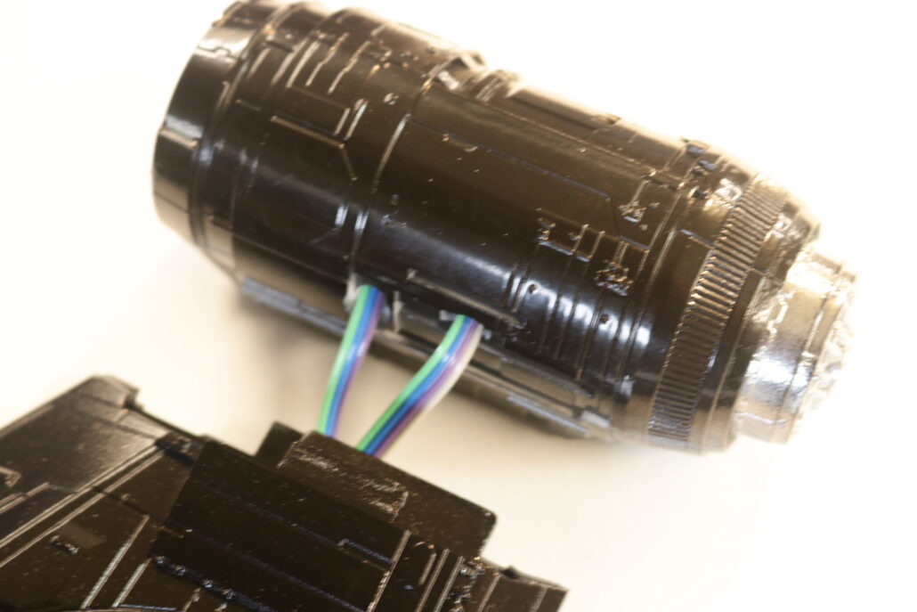
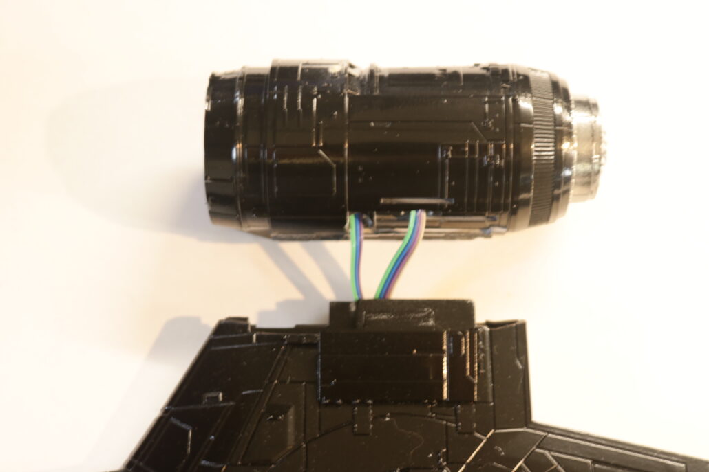
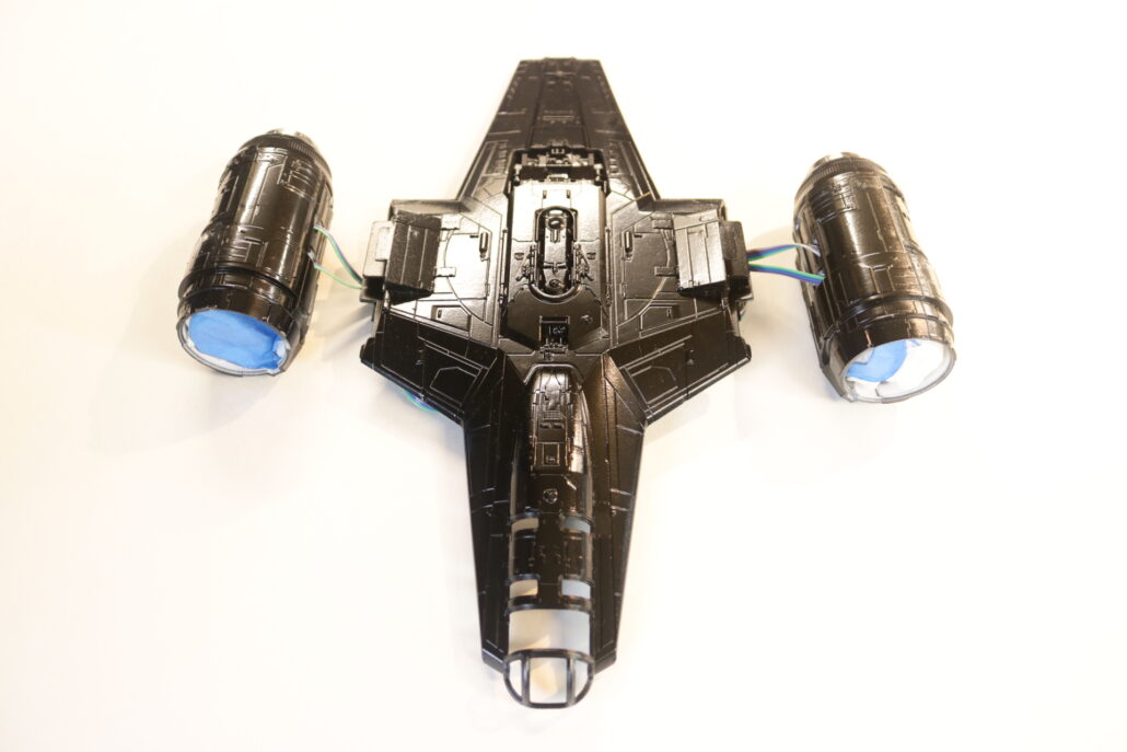
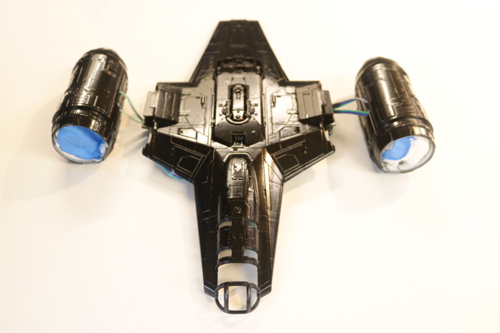
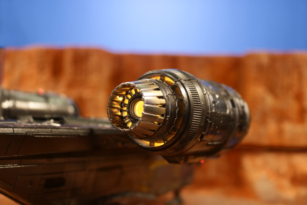
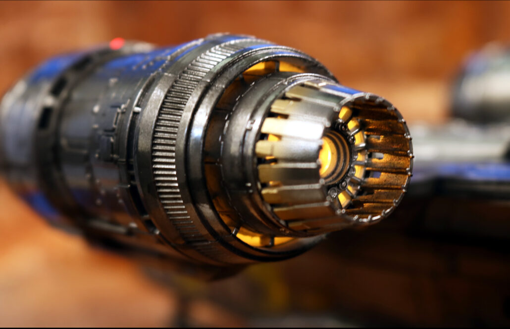
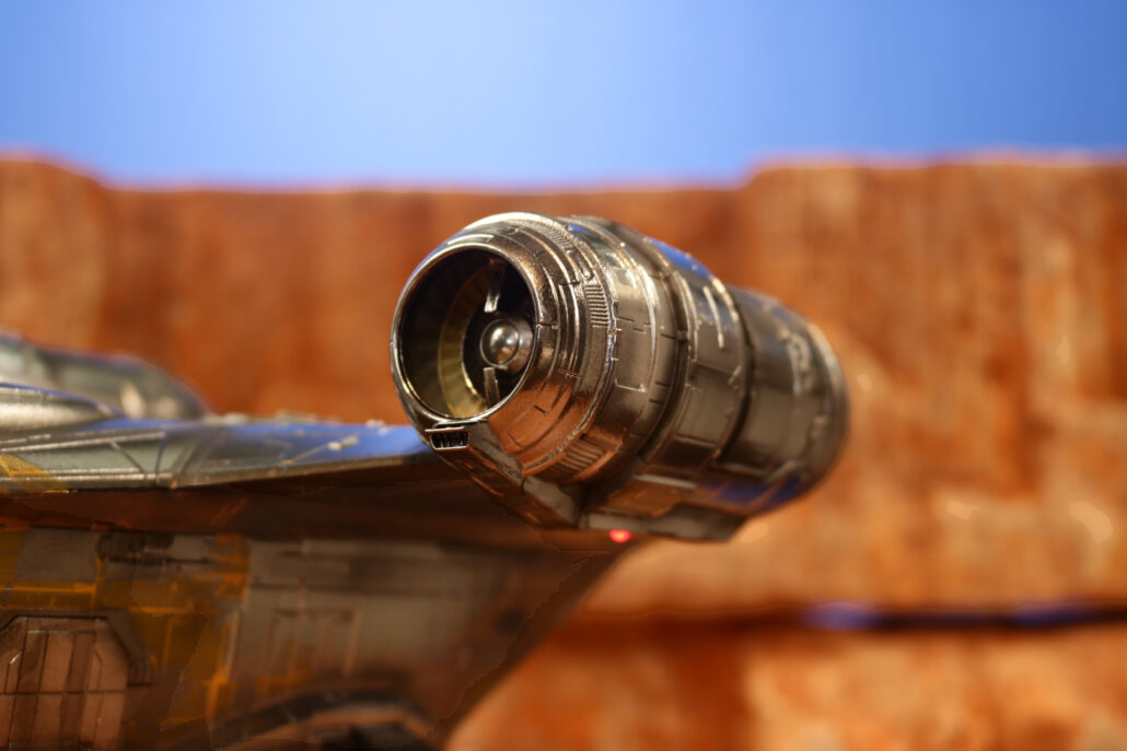
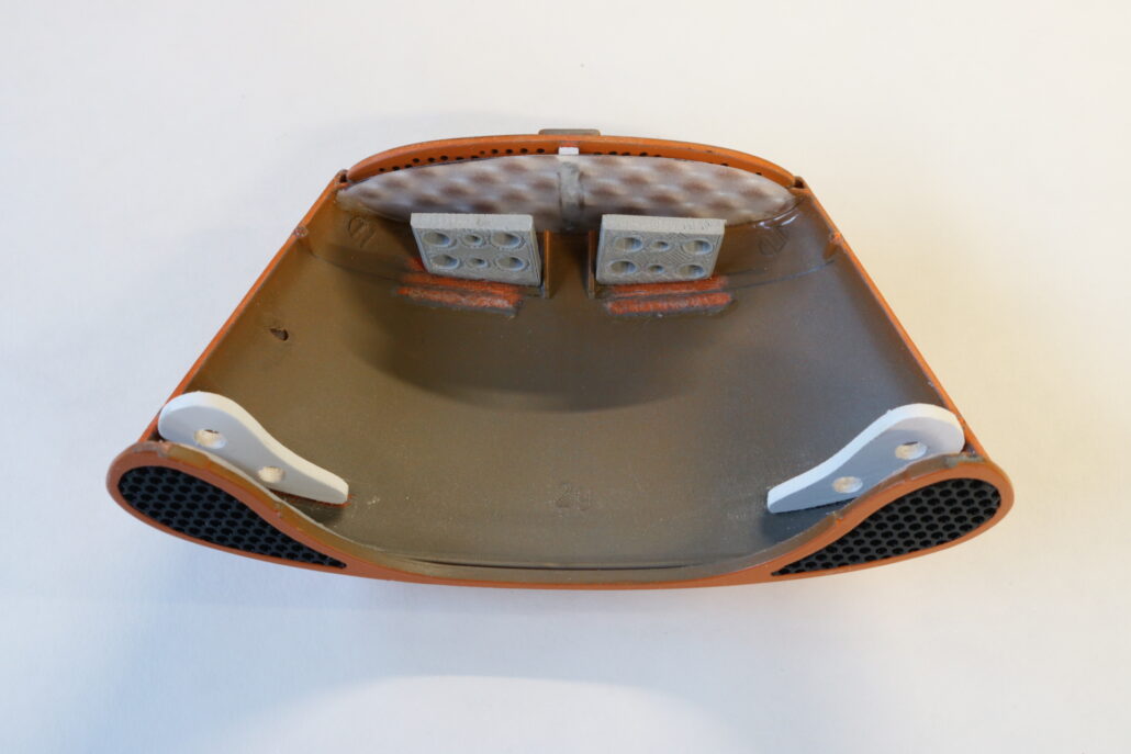
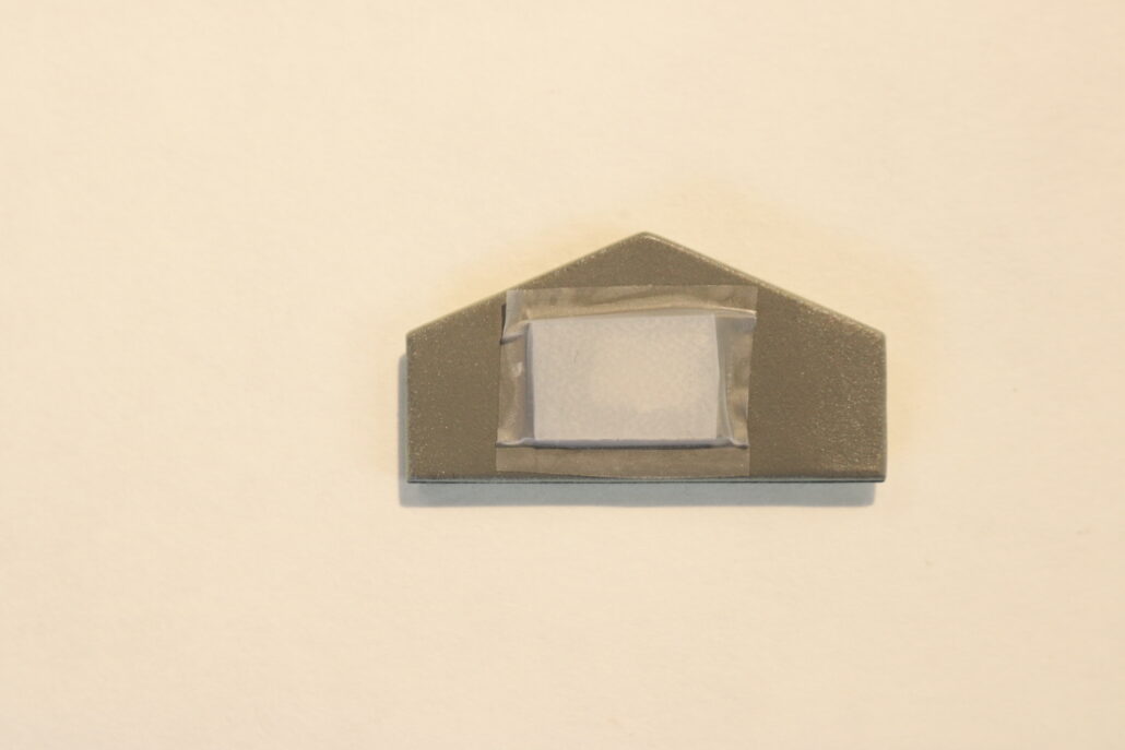
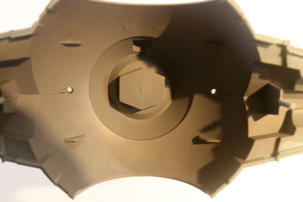
Engine Lighting:
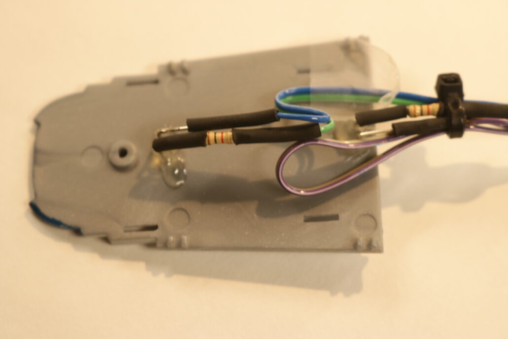
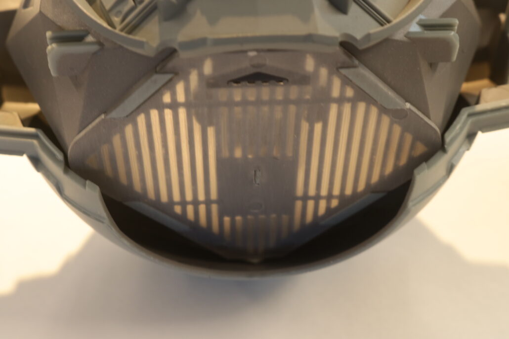
The two rear engine lights will be mounted on the back side of the rear main body. You will want to pre light block & mount the clear lens parts in place before installing. The leds will need to be pre fitted in place before you put the interior cockpit inside the rear half of the model. This is a very tight fit & might require some sanding & trimming of the cockpit corners to allow a proper fit of the cockpit interior. The red leds will need to be slightly bent towards the wing strut since the fit is so tight. Use the 220 ohm inline resistor set up for each leds & connect to ports 10-11 on the circuit board.
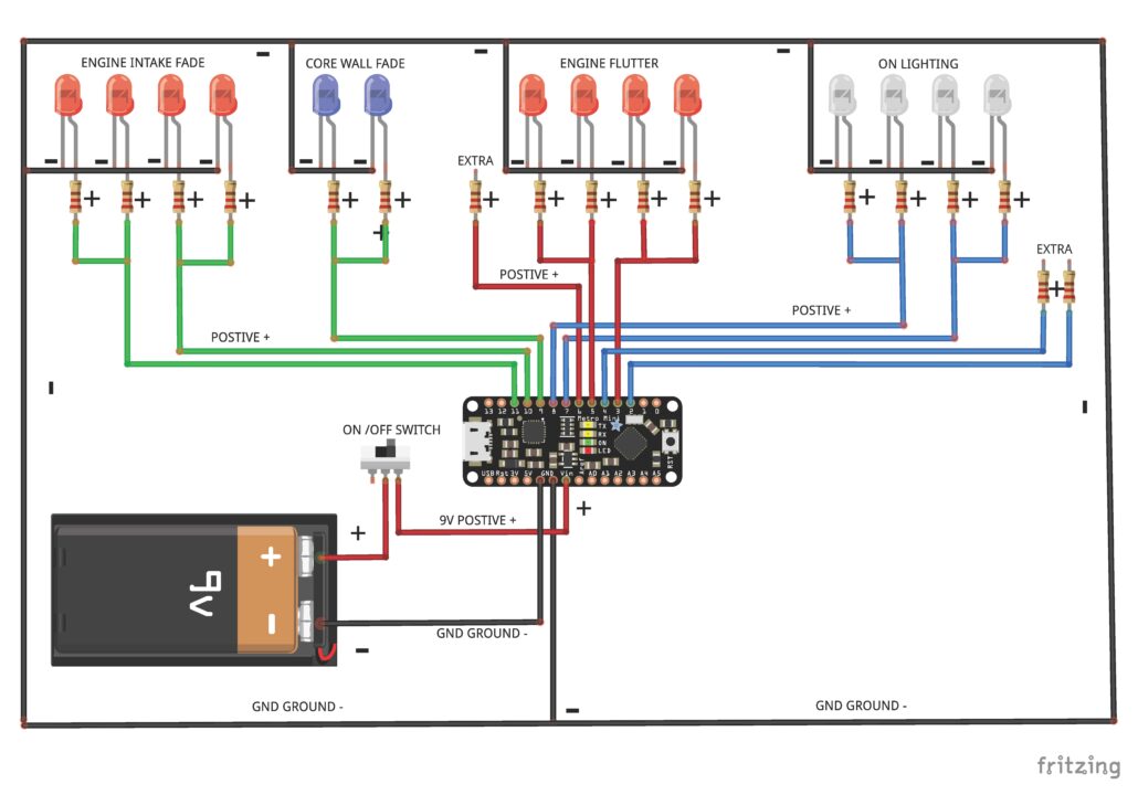
Wiring Diagram:
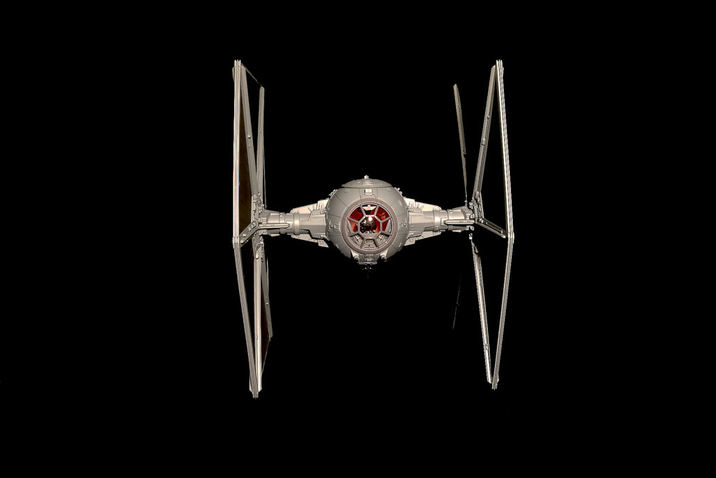
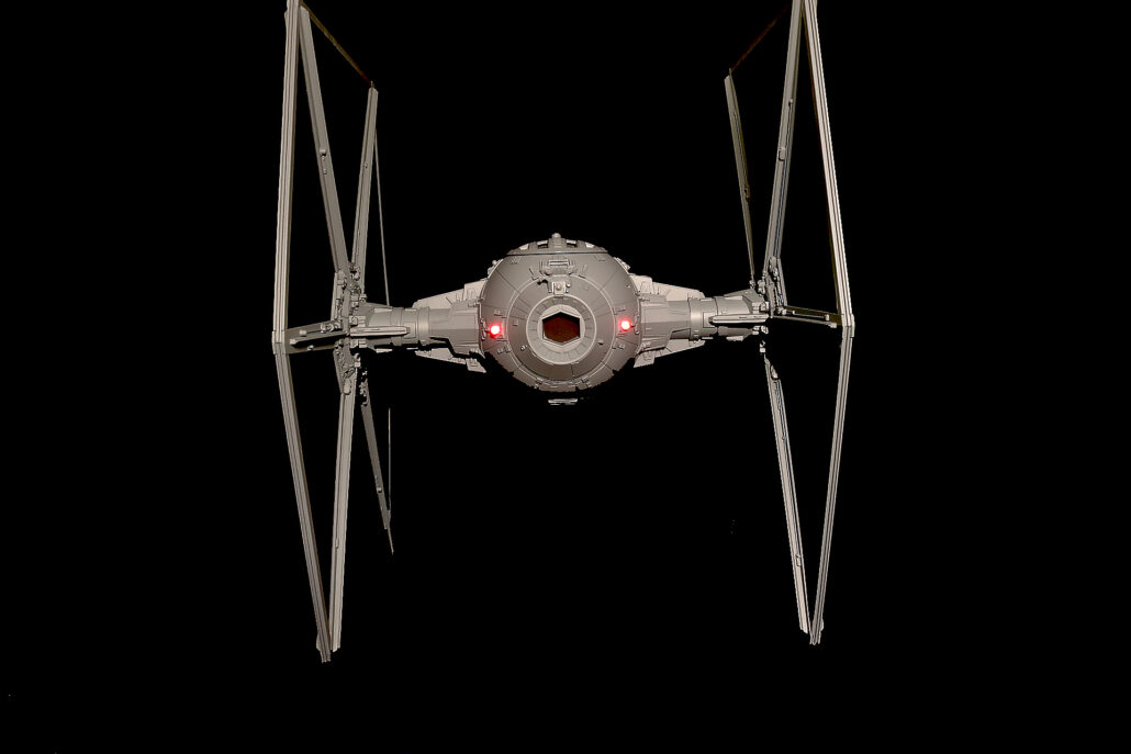
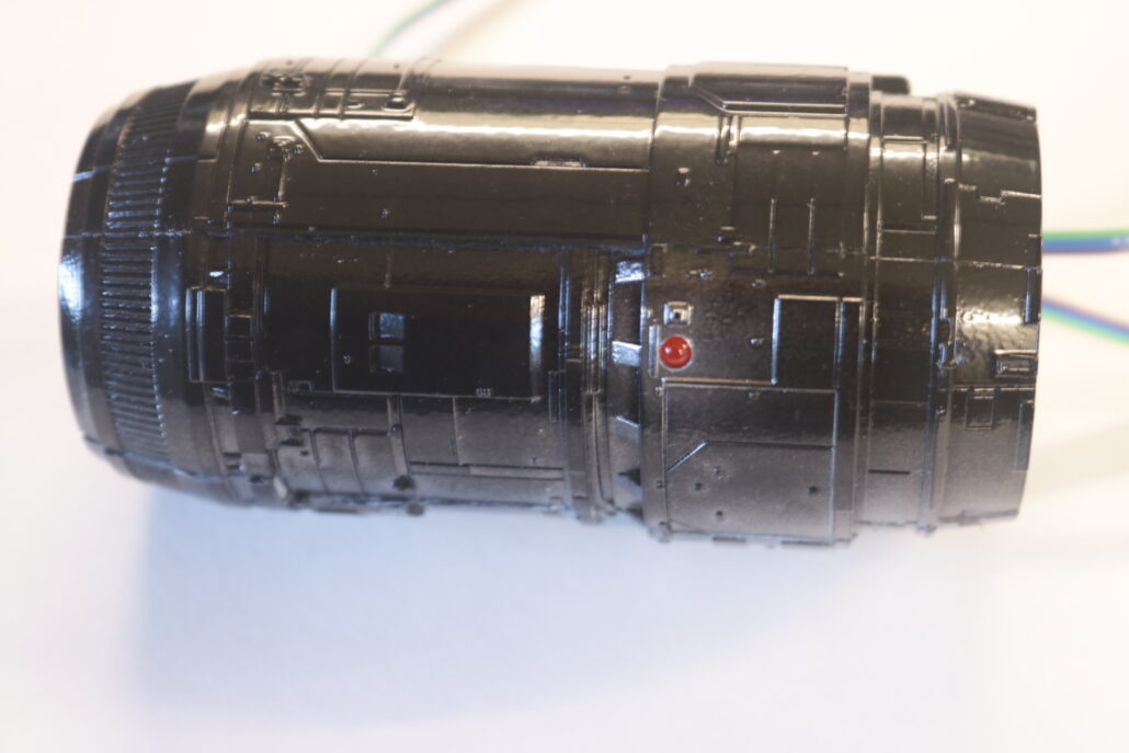
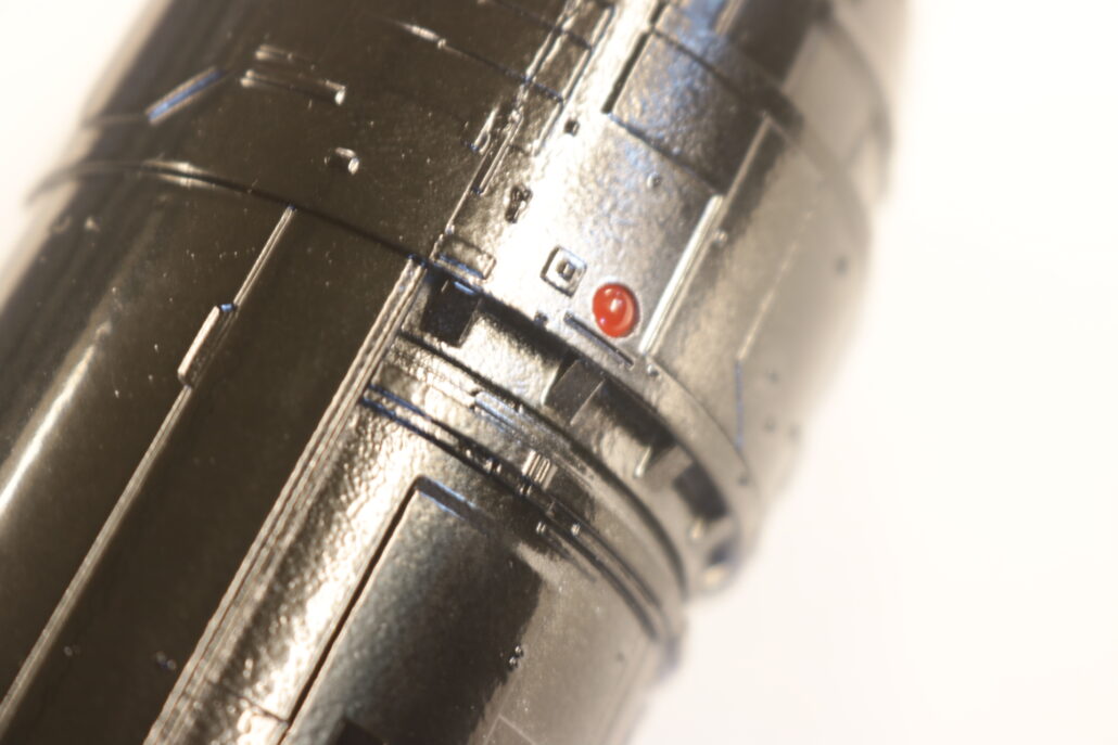
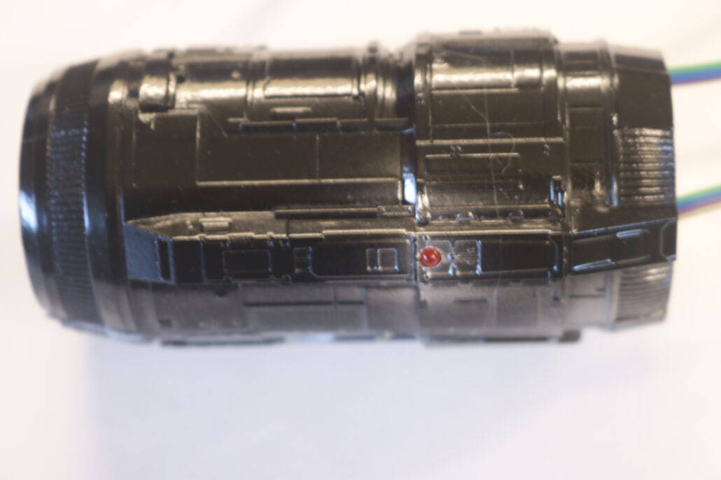
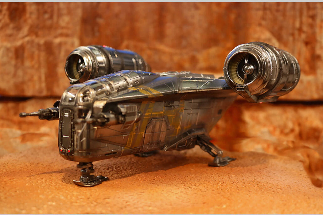
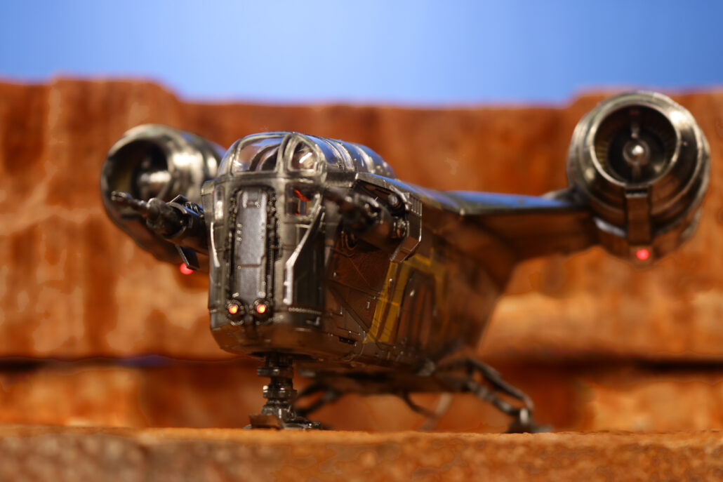
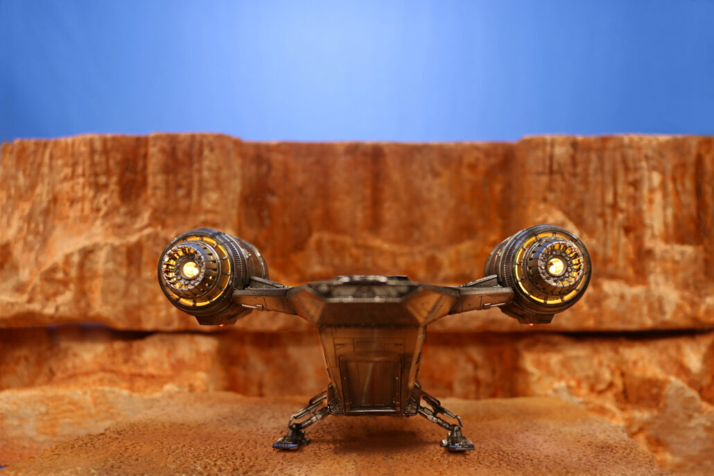
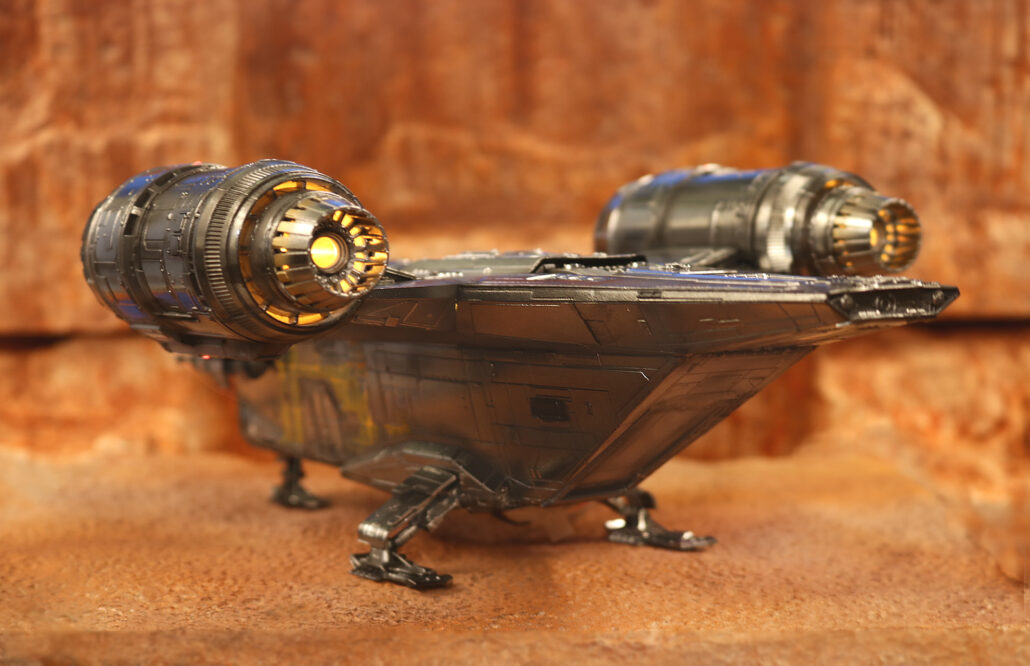
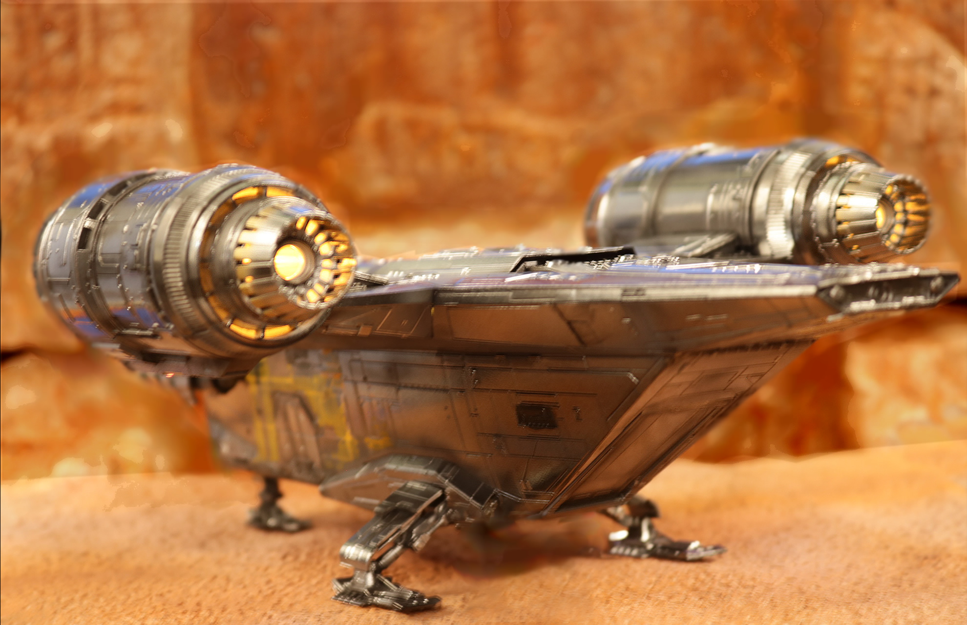
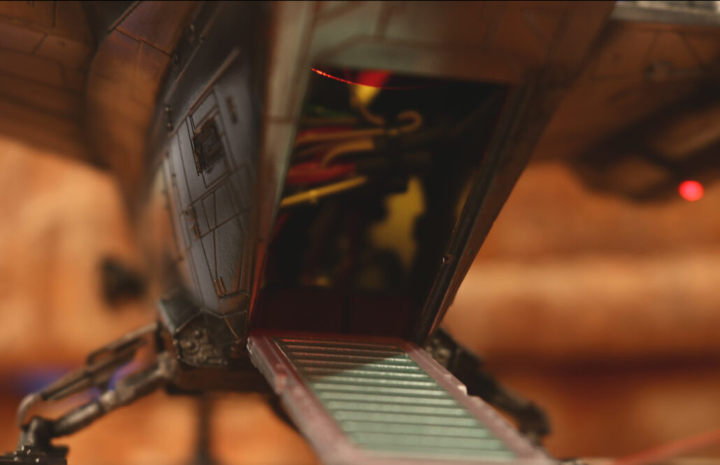
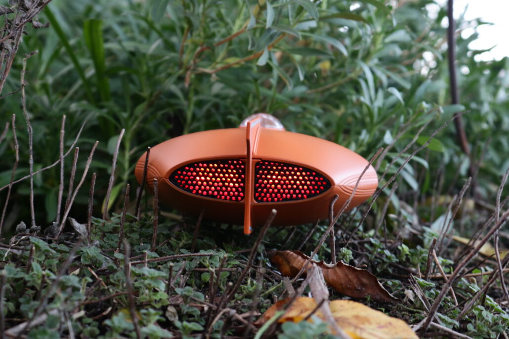
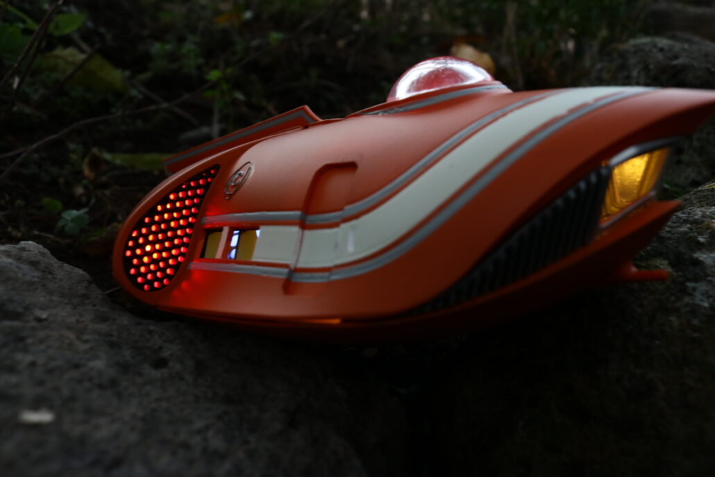
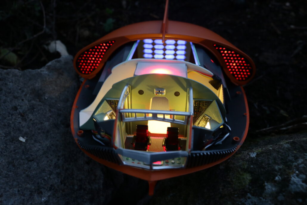
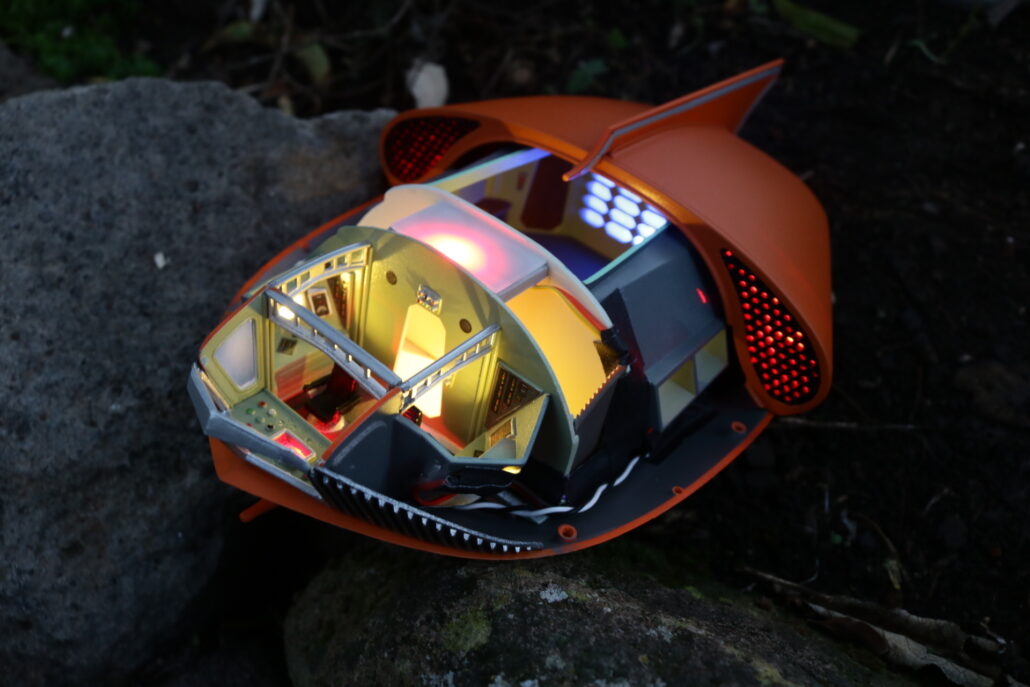
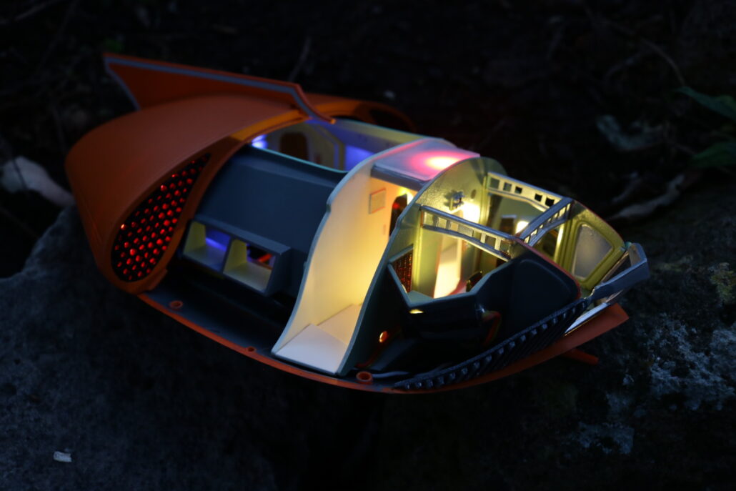
Finished Photos: