The Invaders UFO Light Kit
Getting Ready:
In this blog I will be going over the basic building modifications & fit work to support the Invaders UFO lighting kit. Please remember that due to the small scale of the model kit, the interior is unsuitable for use in the fully-lit version… however, if only lighting the five outboard dome lights you may be able to also light the interior.
Note: VoodooFX has no control over third party aftermarket parts & accessories availability.
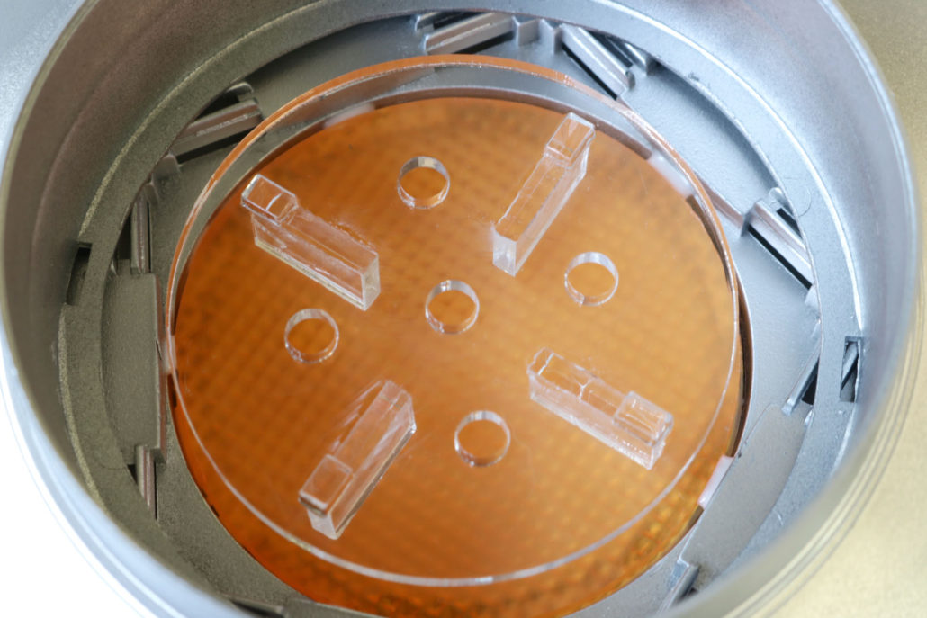
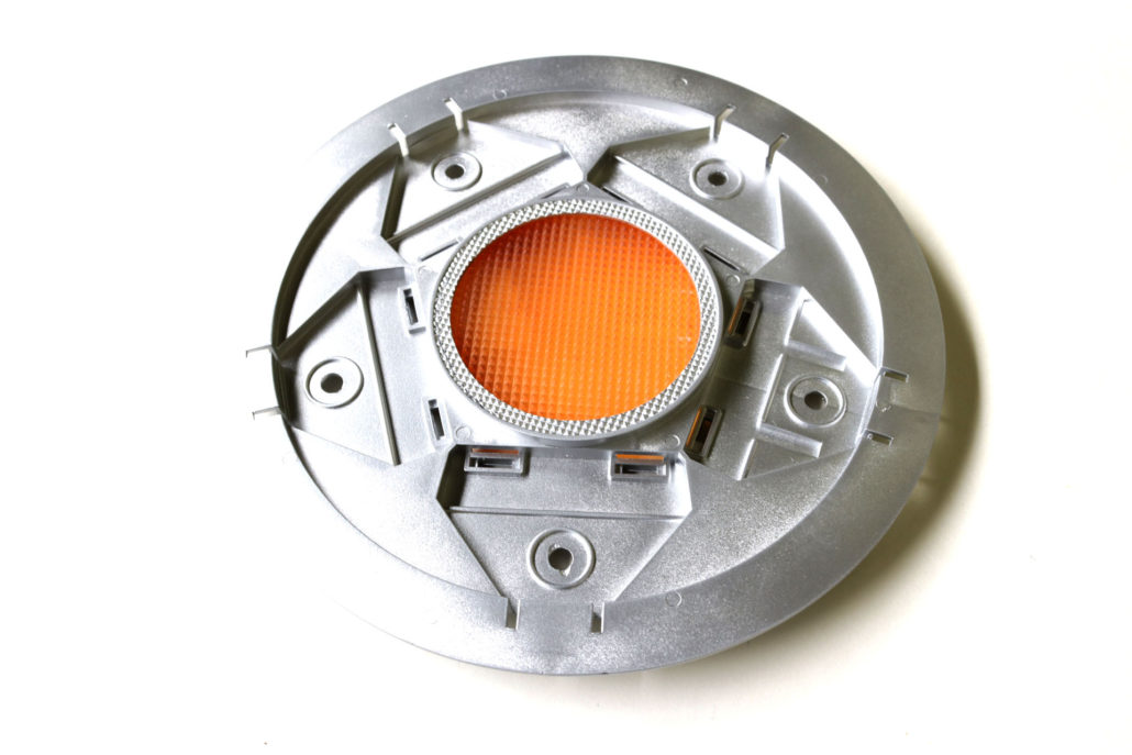
First getting started, the main central engine area will need to be cut out to support the new lens part. You will want to leave a small ledge (around 3/16″) of the original engine grid to rest the new lens part on, this will be mounted on the inside of the main engine chamber. The five outer domes will also need to drilled out at 5mm to support the green LEDs. The green LEDs will need no in-line resistor, as they are already pre resisted. (NOTE) The green LEDs will need to bent at a 90 degree angle to save as much room as possible.
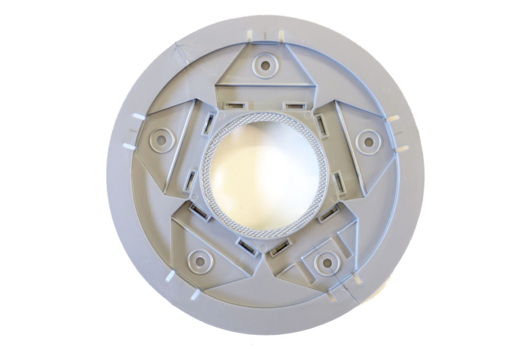
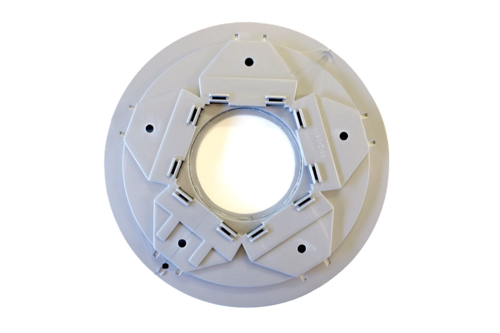
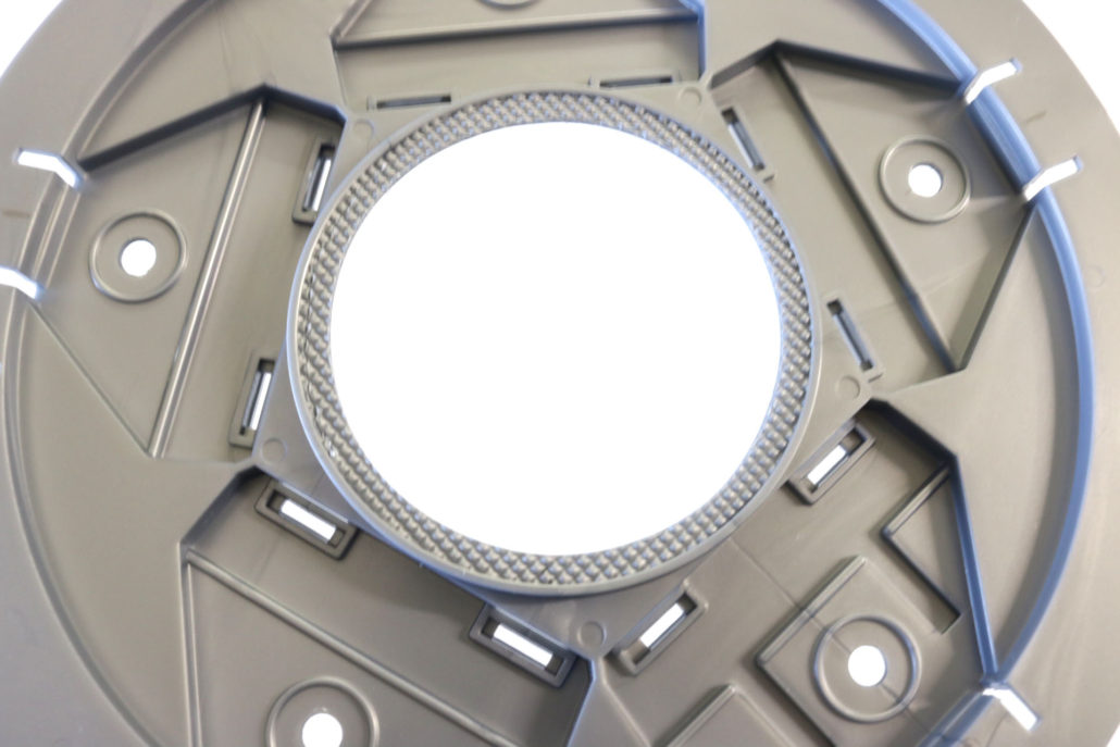
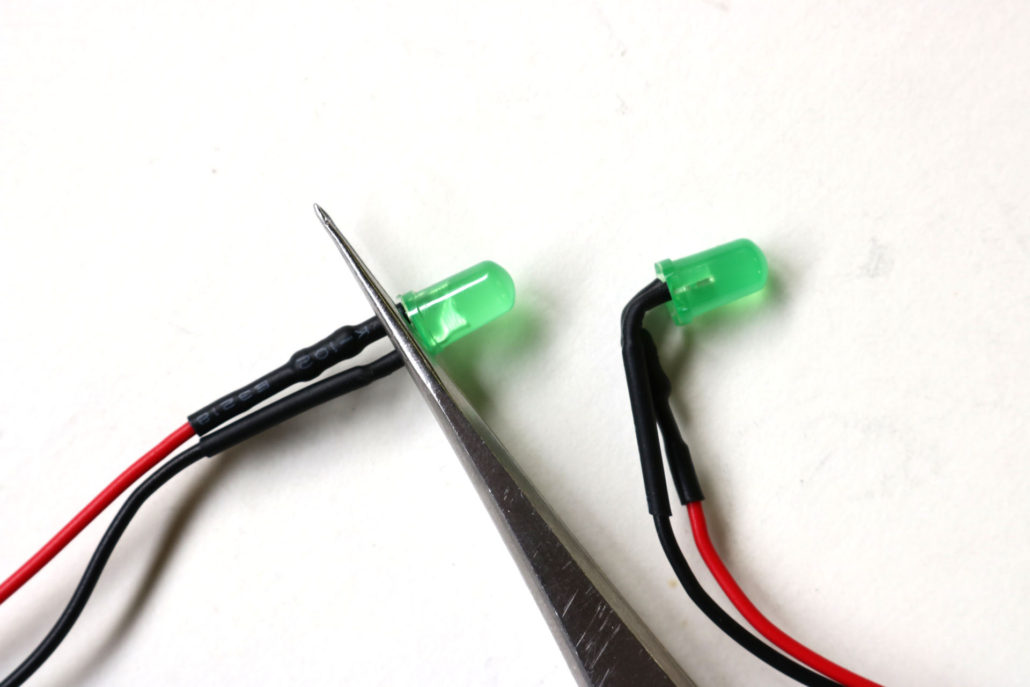
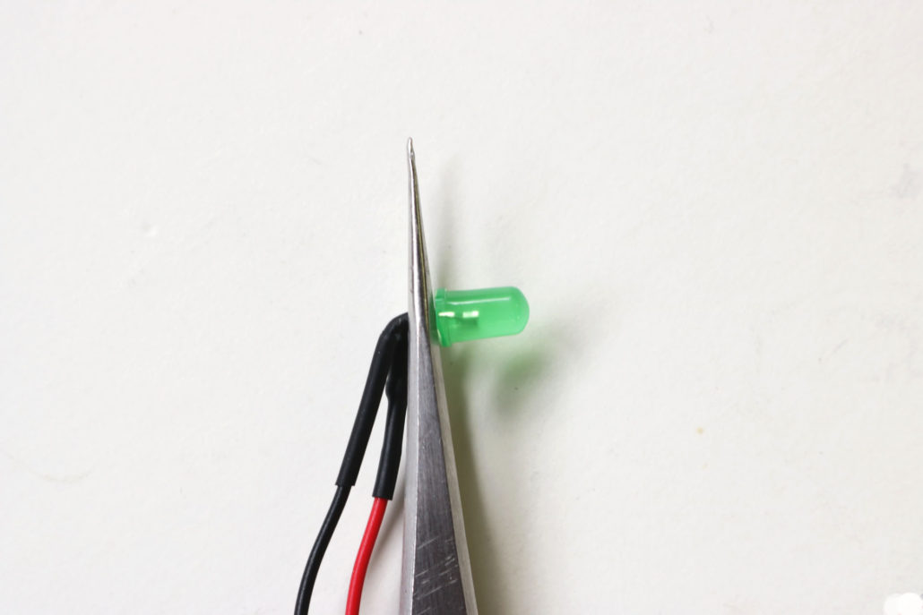
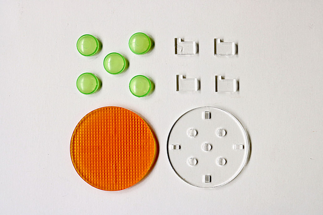
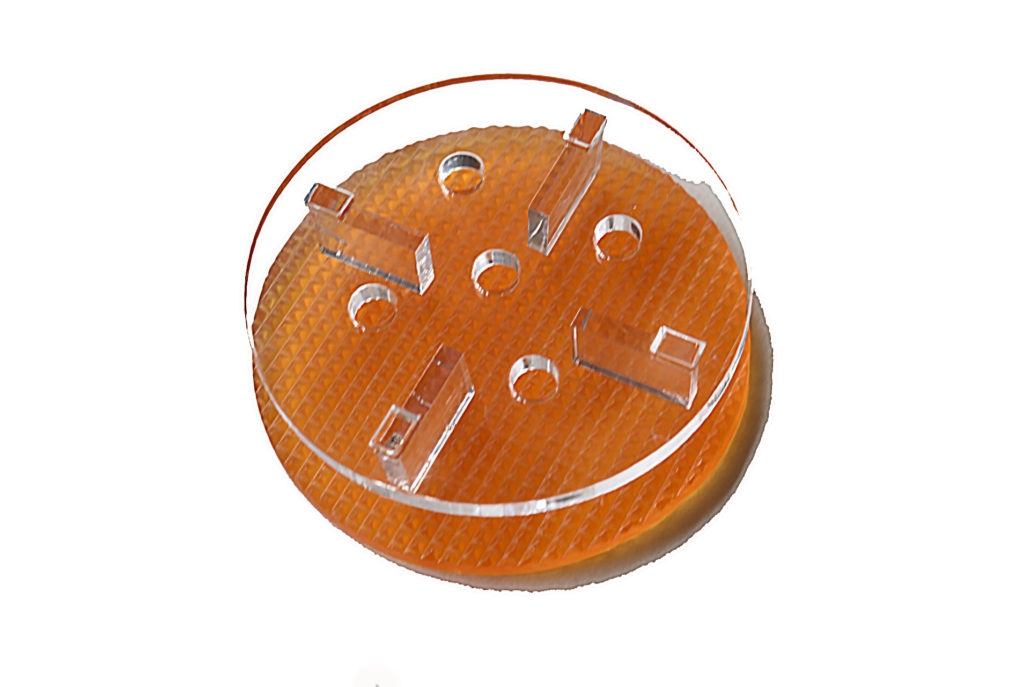
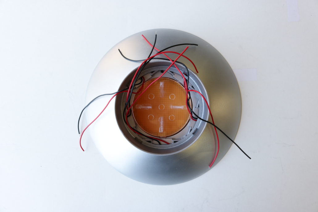
After pre-bending all the green LEDs, they can be threaded into the 5mm holes you already pre drilled for the domes. When mounting the LED, you will want to test them with the green dome lens to make sure that they don’t get pushed too deep in the hole, making them bottom out on the lens cover. Use a small amount of hot glue on the LED for permanent mounting. It’s a good idea to black out the LEDs to help prevent light leaks throughout the model. This is also an opportune time to get the main engine lens & LED support bracket built. Prebuild the clear acrylic support first, glue together & let dry. Mount the lower lens (with the ‘bumpy’ side down) towards the bottom of the model. Use either white glue or clear silicone to mount the lens, and let fully dry. After drying, mount the LED support on top of the lens, and check the cross pattern for alignment.
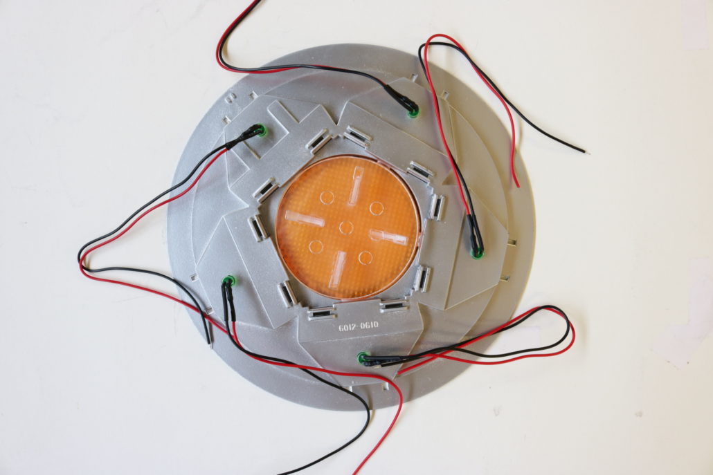
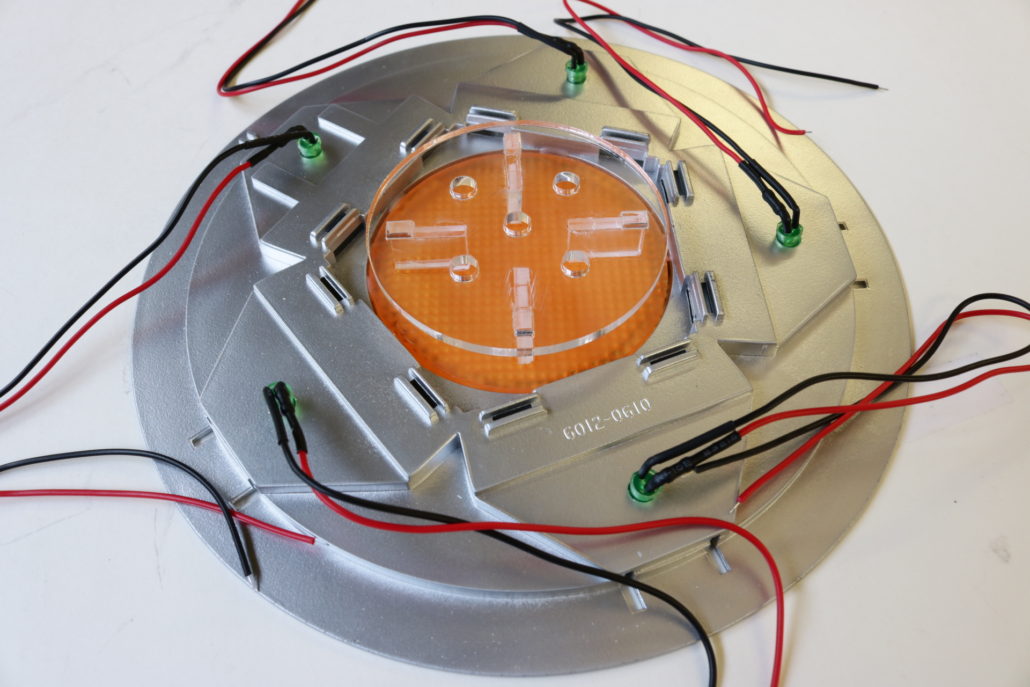
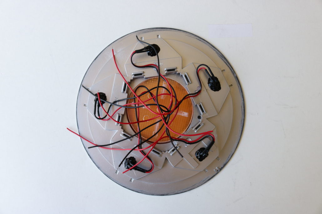
The dome lights can be either tied into direct power, or can be hooked up to the master circuit board using pinouts 0,1,2,4,7. Further info on the circuit board layout is provided later in the article. After mounting lens and LED supports, test all the dome lights for operation. Carefully route the dome lead wires into the center of each landing leg, via their mounting tab. Keep in mind, you will need to make a small “S” turn in the wire to prevent kinking of the LED. Use a small amount of hot glue to hold the wires in the center. You may now mount the upper half of the model to the base plate.
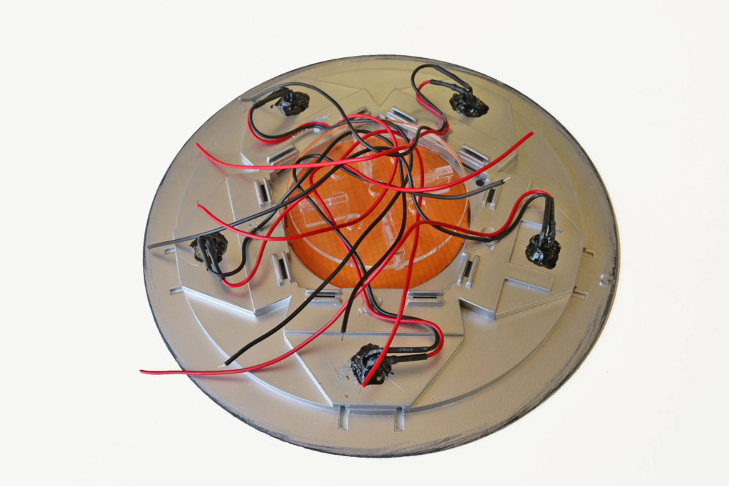
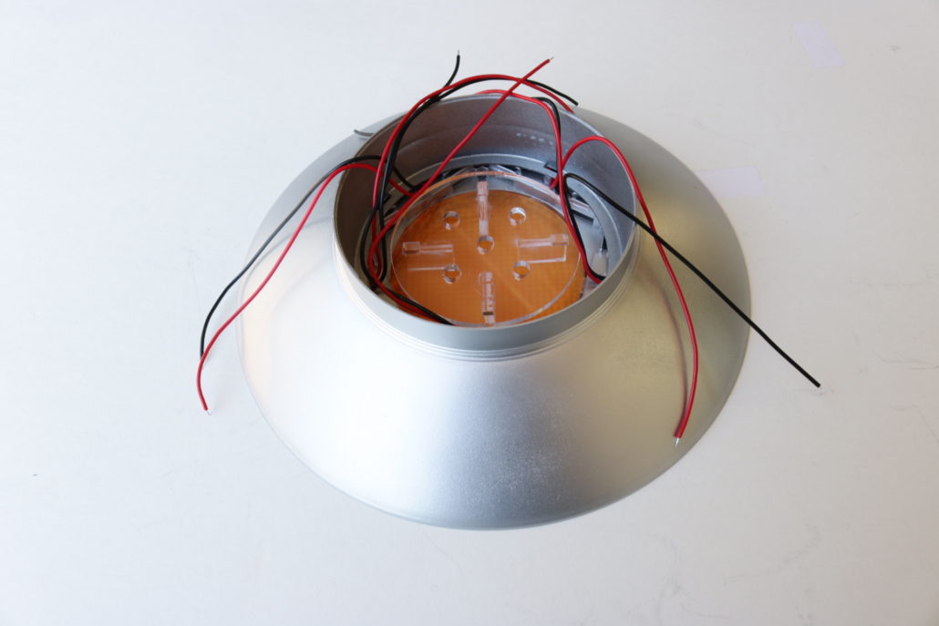
The next step is mounting the five engine LED’s. These LED’s will require a inline resistor on the positive side of the leads. The LED’s will also need to be bent at a 90-degree angle for fitting purposes. The engine lights are powered directly to the circuit board using pinouts 3,5,9,10,11. Again, further information on the circuit board layout is provided later in the blog. Once you have pre-fabricated the LED’s with their resistors, test each LED for operation. Carefully bend each LED at a 90-degree angle & mount to the LED support bracket with a small amount of glue. Run wires long outside the top of the model, these will be cut down & soldered to the circuit board in the final assembly.
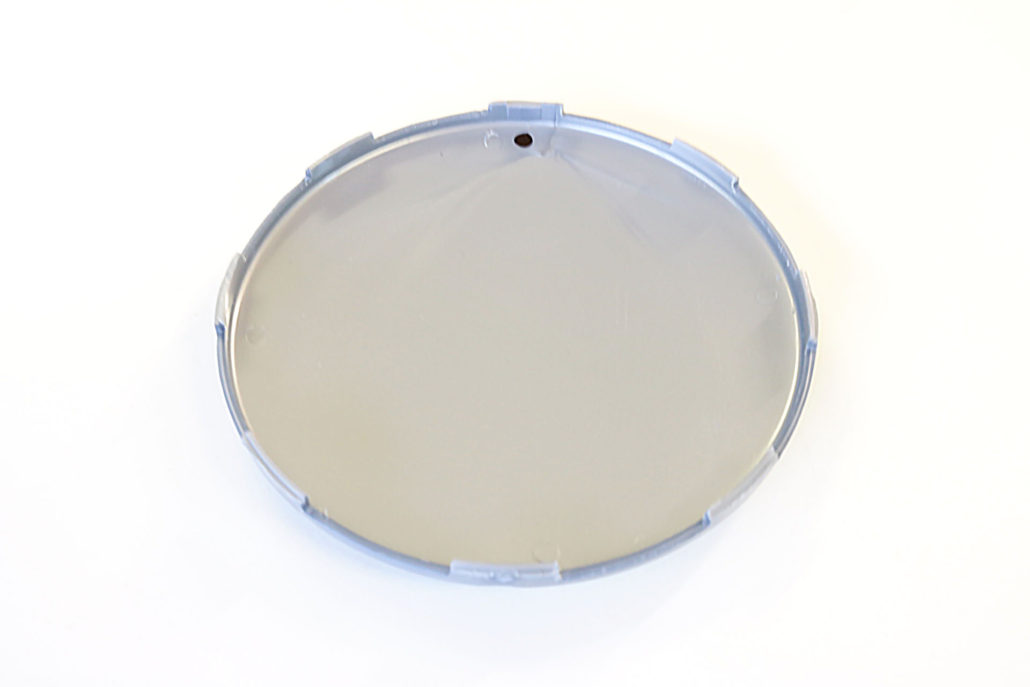
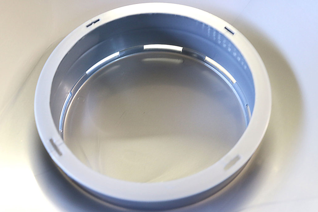
The top cover with the slot windows can be made using two different methods. Since the new kits comes with a clear top dome, the window slots can be masked off and painted. If using the clear part, make sure to mask of both sides of the slot window inside & out. If you’re using the standard top, you will need to remove the plastic around the window slot area. It’s very important to be very careful when removing this area around the window, as it is very easy to over cut the window frame. You will also need to install a 2 1/4″ piece of tubing in the center of the dome, to support the mounting of the slot strip. The kit also has a small piece of diffusion material that is mounted around the inside of the window slot. Cut to size and mount with a small amount of hot glue.

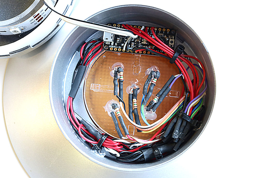
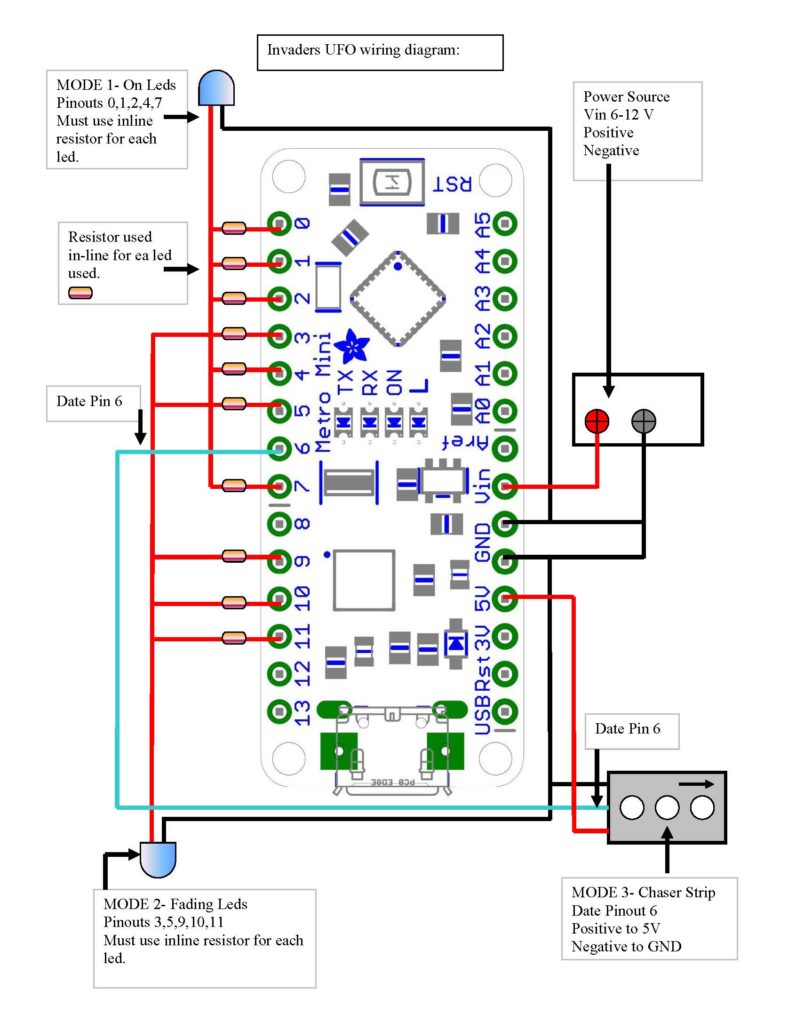
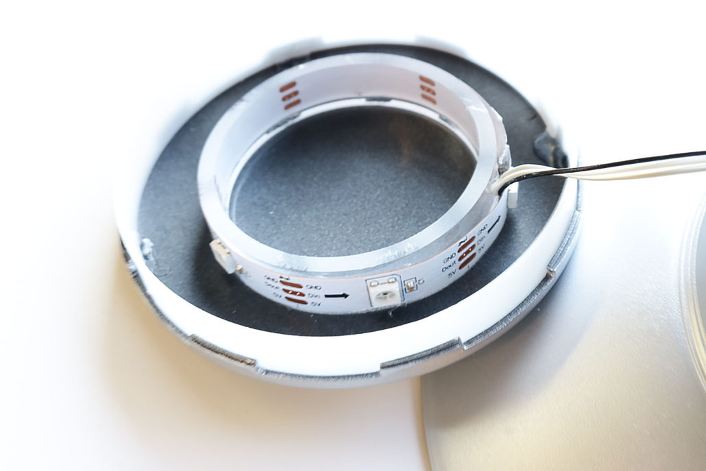
The circuit board hookup is next. The best way to get an understanding of the board is to study the wiring diagram. In a nutshell, the circuit board is based on series of pinouts, each pinout being a positive power pin that requires a inline resistor to protect the LED. In the diagram, the image shows only one LED, but it will support a maximum of ten LED’s for this project. Mode 1 is for “on lighting” only. Mode 2 is for all fading lights found in the engine, and mode 3 is for the strip or slot light effect. Mode 1-2 are intended for basic LED hook up, whereas mode 3 is based on one date wire for control. The strip is wired to pin 6, and goes directly to the strip marked “DATE”. Positive & negative power are connected to 5V positive & GND on the circuit board. “VIN” goes to the power source with GND direct, to the negative side of the main power source. If at any time you have trouble understanding the circuit board layout/assembly, please contact me directly.
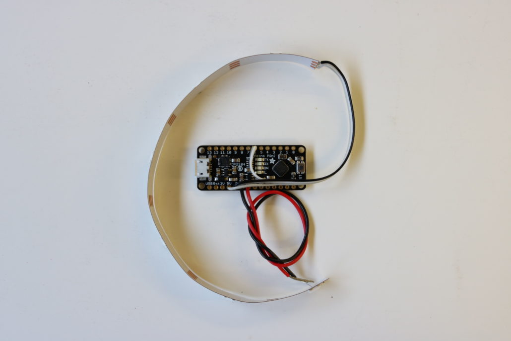
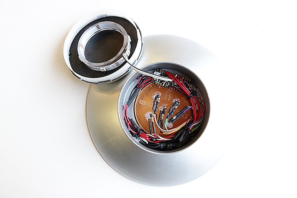
Once you have studied the circuit board, hook up an LED & test the pinouts for operation. At this point, you can also prefabricate the strip and wire it to the board. All other connection points for the LED’s can be soldered to the board when the top half of the model is glued in place. The final install of the circuit board will be tight, and will need to rest on the LED support bracket. The circuit board will need to lay flat, looking up towards the top dome. All the wires will need to be pushed down as close as possible to the LED bracket support. This will help prevent any wiring from hanging up on the top dome when it is set in place. Turn on power & test all locations for operation. Finally, you can use a small amount of white glue to mount the main upper dome part. This concludes the general instructions for the Invaders UFO lighting kit, if you have any questions please contact us directly at:
EMAIL randy@voodoofx.com

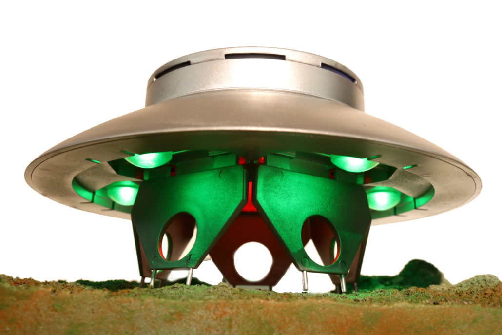
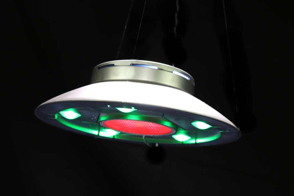
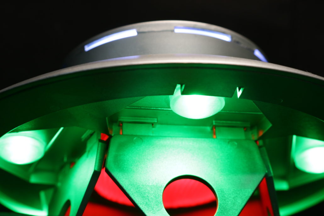
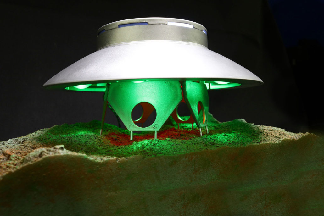
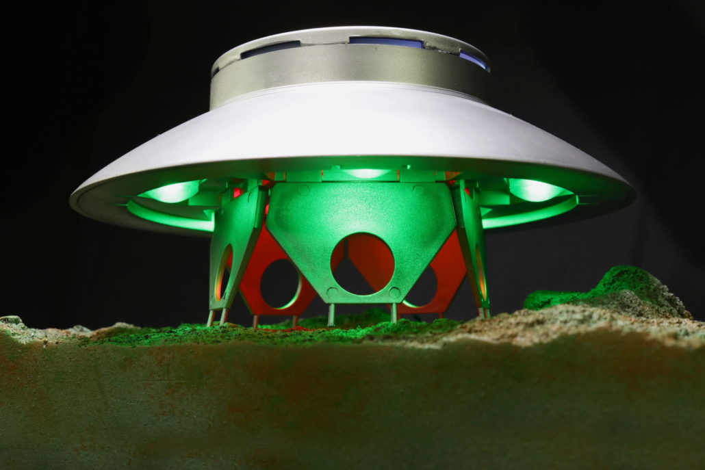
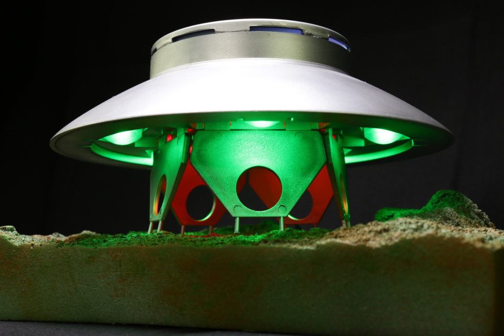
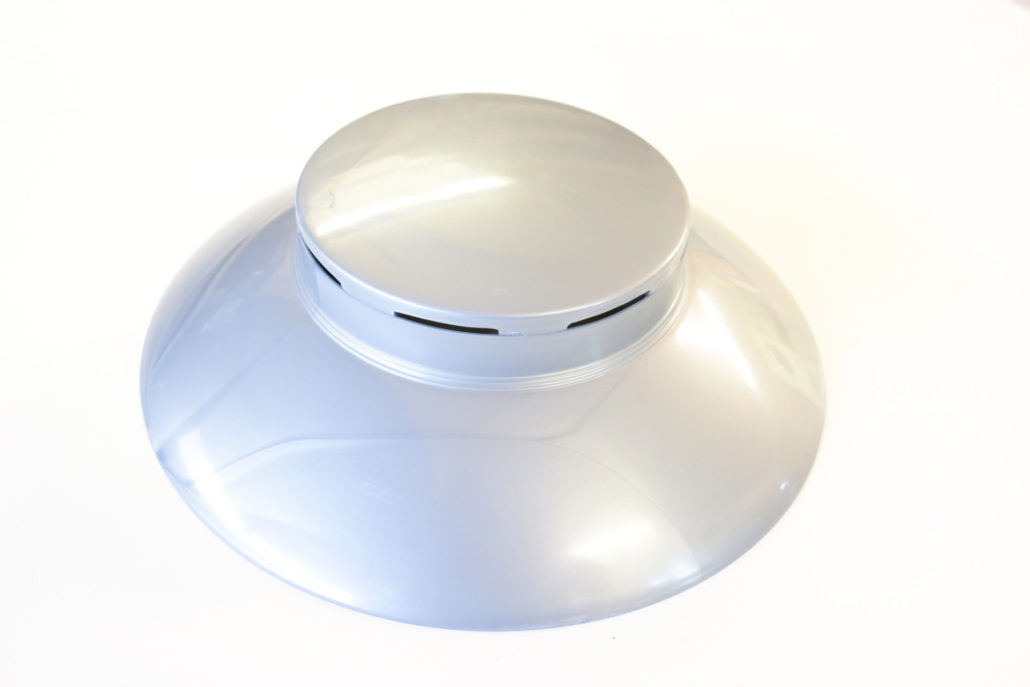
Finished Model