2001 EVA Pod Build Part 1
Getting Ready:
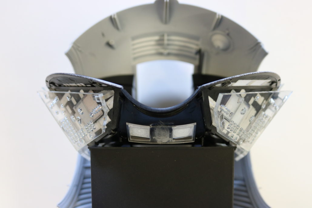
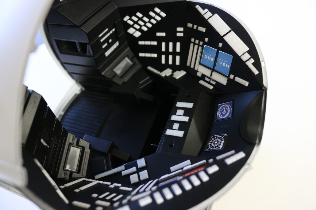
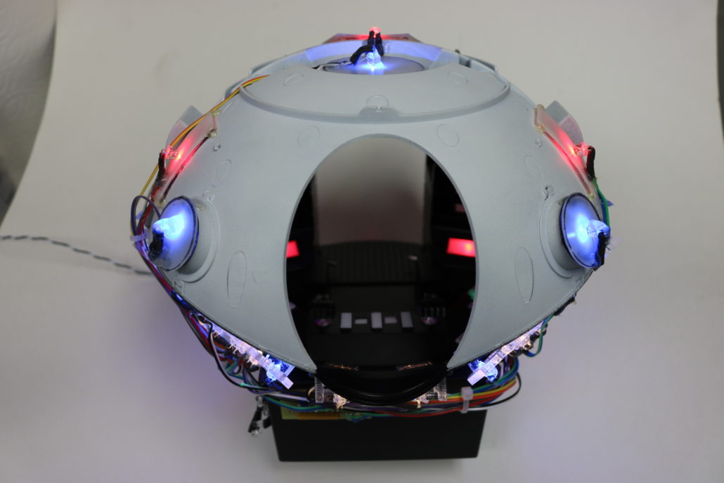
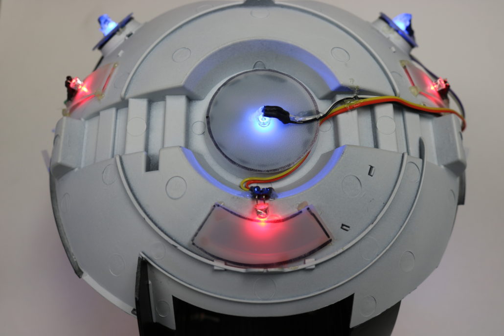
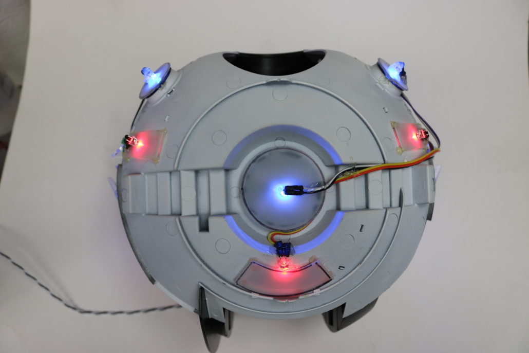
Building & lighting the new 1:8 scale EVA Pod from Pegasus Hobbies & Moebius Models. I received a test shot of this model and was blown away at the scale & design elements of this kit. As usual Moebius Models & Pegasus Hobbies have created a amazingly accurate model kit with enough room to fit electronics in it. I started by braking down the bulk body parts & getting myself familiar how the model fits together. In most test shots there are no instructions or decals with prototypes and sometimes it might be missing a few parts here & there. In that case, the model was pretty straight forward and all the main parts were in the kit. However, I did make some mistakes here & there. Lets get started with the lighting, once I had all the interior panels figured out where they fit I had to address the problem of the button lights. The first idea was to tryout bulk strip lighting , which did not work. The second try was using a wide angle led, this had some good qualities but again, had a washed out effect. So I then tried out a 3mm led for the buttons & it gave the desired overall effect. Note: VoodooFX has no control over third party aftermarket parts & accessories availability.
Using Aftermarket Parts:

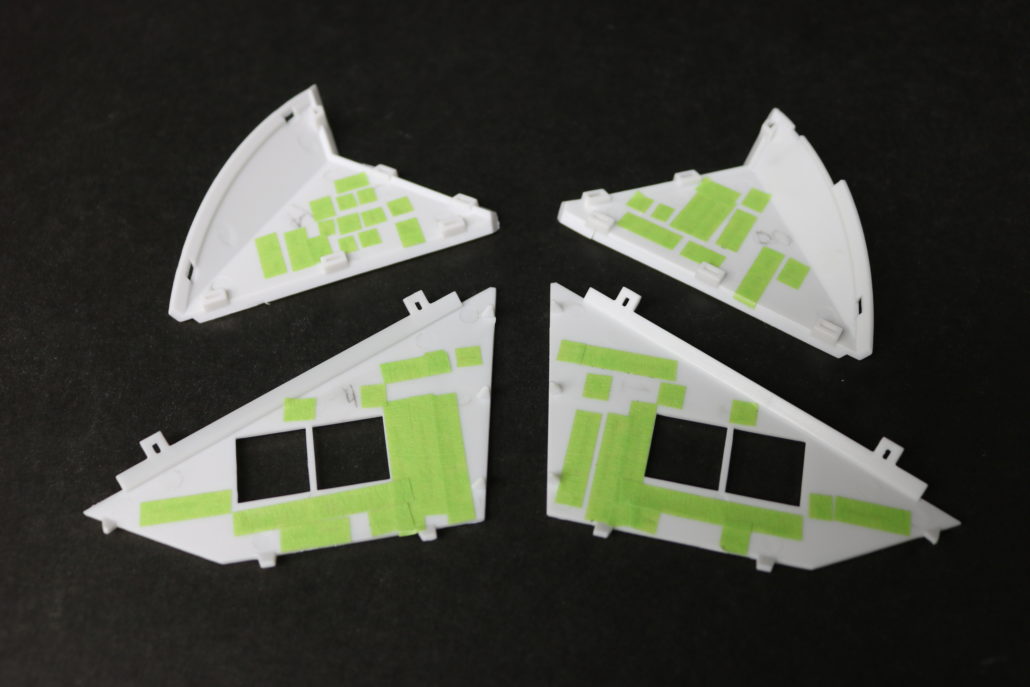
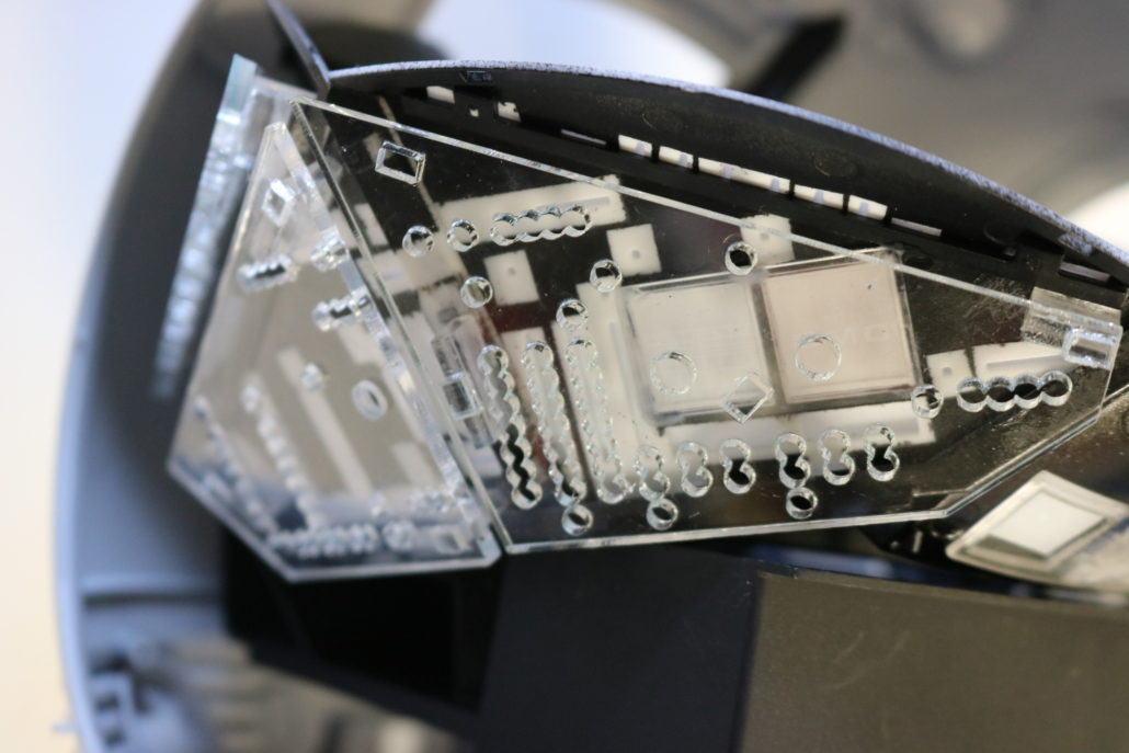
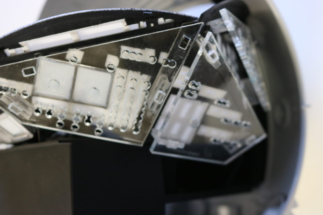
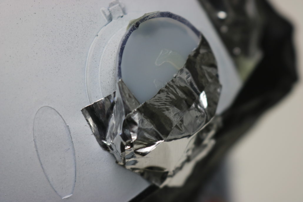
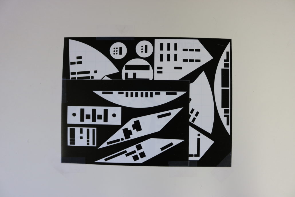
Mounting Led Supports: After pre light blocking & installing the vinyl overlays I was ready to starting build the interior. Once the interior was assembled I made any touch ups at this point & was ready to move on to the acrylic support for the led install. The lighting support are ideal for lighting this model, I pre built the supports by using a small amount of acrylic glue. Using the stand offs “T & L” provided in the kit. Scuff the areas on the back side of the panels to mount the supports, you can us a small amount of CA glue for mounting.

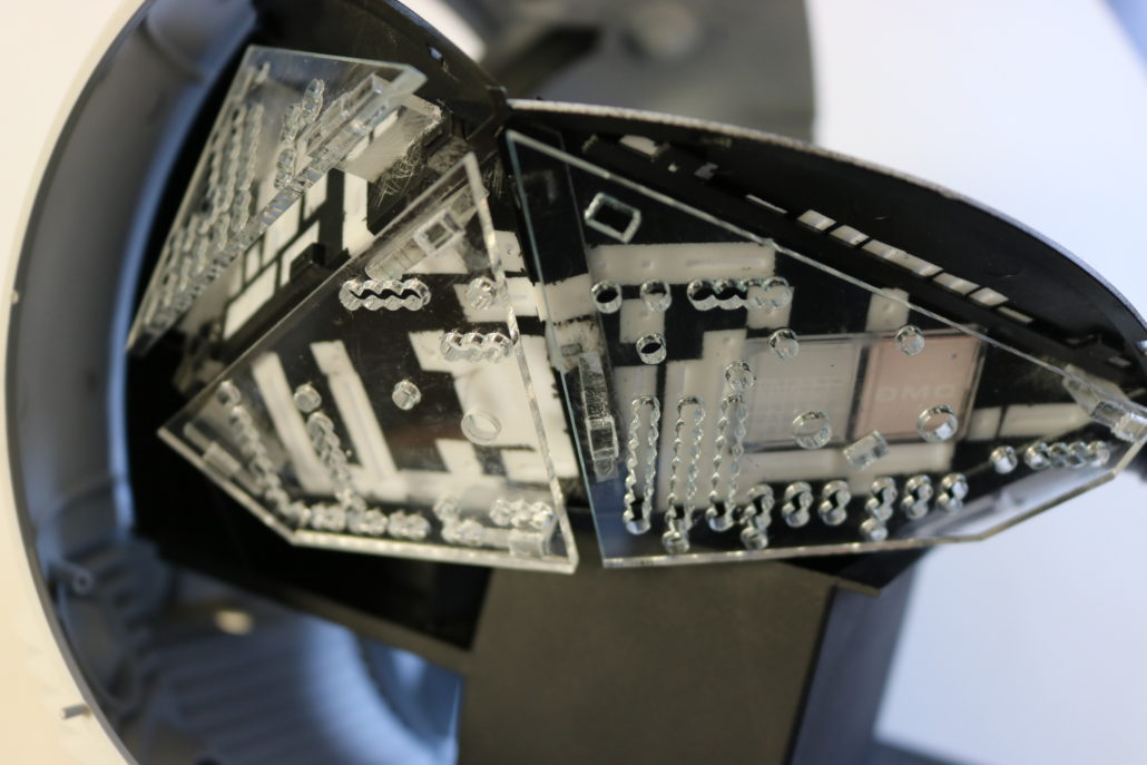
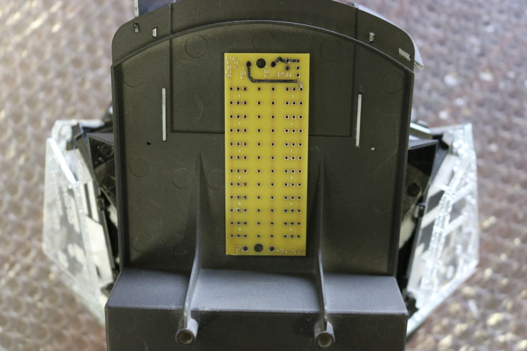
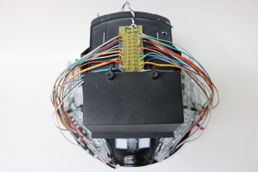
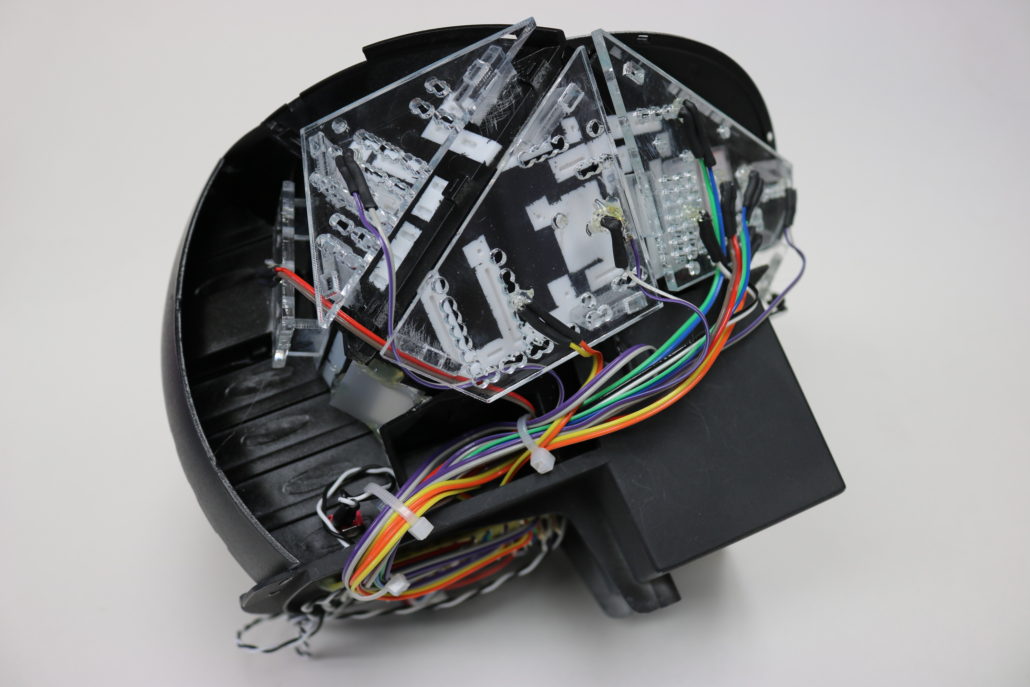
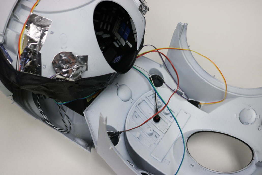
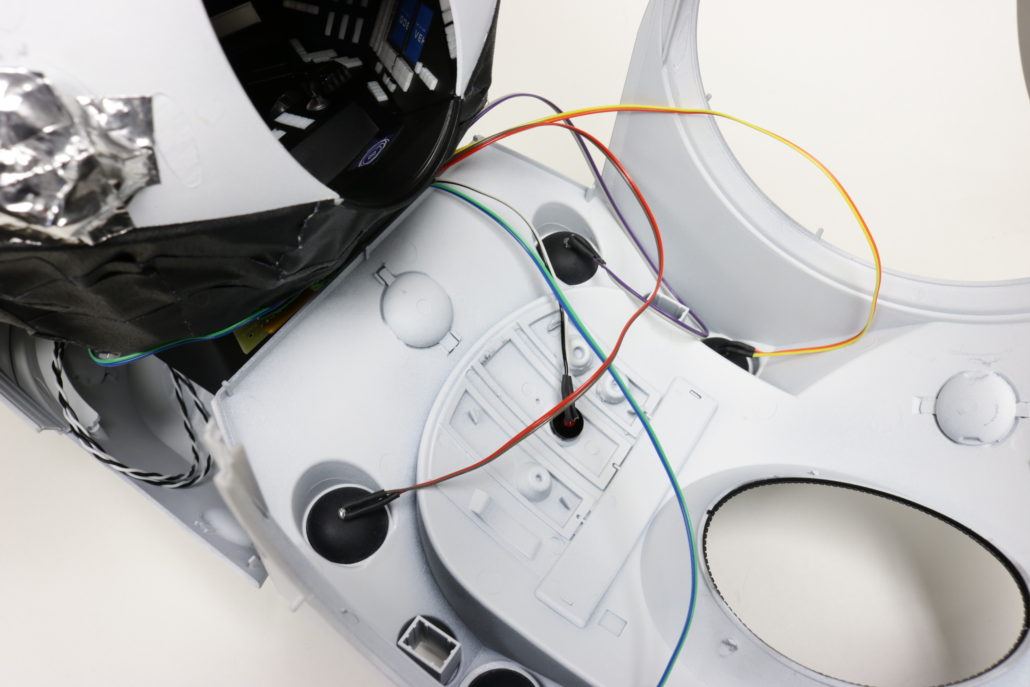
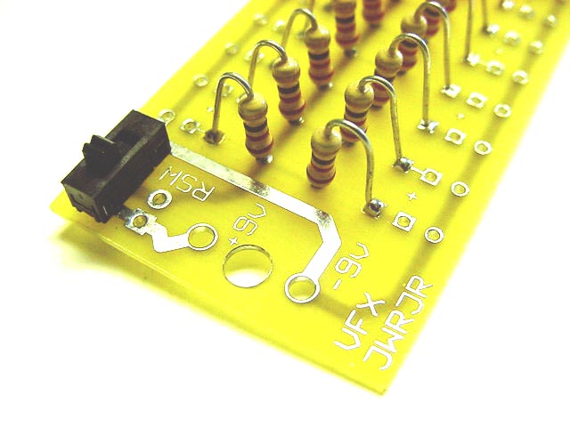
Circuit board & Leds: Most of all the electronics can be prebuilt outside the model & fit up to the interior before installing into the main body. I always start by building up the board first, this is done by soldering all the resistors on board & making any power leads or switching set ups. Now by taking some crude measurements at where I want to mount the circuit boards & where your leds are going to be mounted I start prefabbing the pre cut wire lengths to the leds. Once I have a few on the board I test the circuit to make sure its working properly. NOTE: I found it’s better to mount the circuit boards on the bottom of the back half of the main shell (this is a better location then the interior bench).


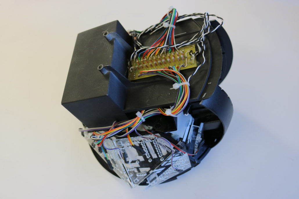
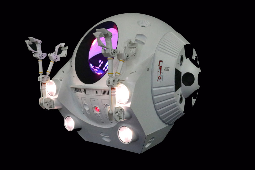
Main Interior Mounting: After all the led lighting is mounted in desired locations I suggest to run a short burn in test. A burn in test is where you run the lighting for a few intervals, I start by running it for 10 minutes & rest for 10 minutes, then run it for a 30 minutes & rest for a 60 minutes. After you have done these tested the chances of a burned out led or a loose connection will show itself in the burn in period. Another good suggestion, is when performing these tested is to lightly tug the wiring here & there to insure the connections are tight. (a loose connection can come back to haunt you when the model is all closed up.) I will go into detail regarding the front head lights & Hal 9000 lighting in part 2. As always any detailed questions can be best answered by contacting me directly by phone.


BUILD GALLERY