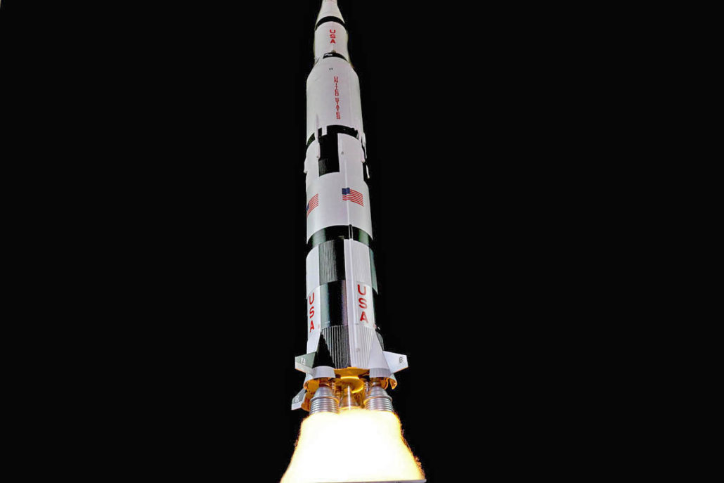
Saturn V Engine Effect

Getting Ready:

Welcome to the Saturn V engine lighting and effects blog, where I’ll be discussing the electronics & general fit instructions in this build.

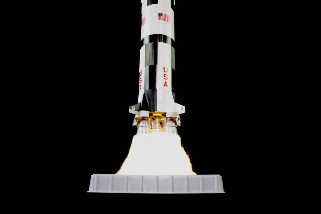
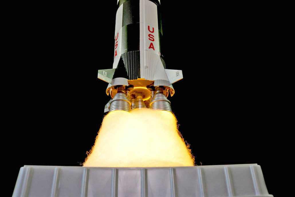
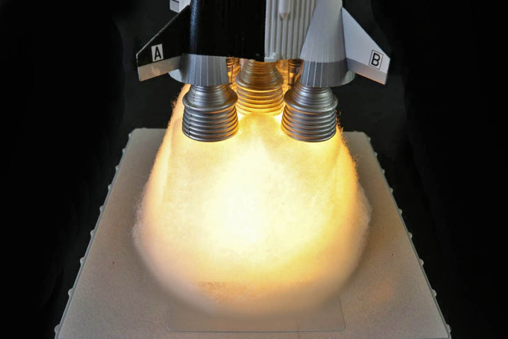
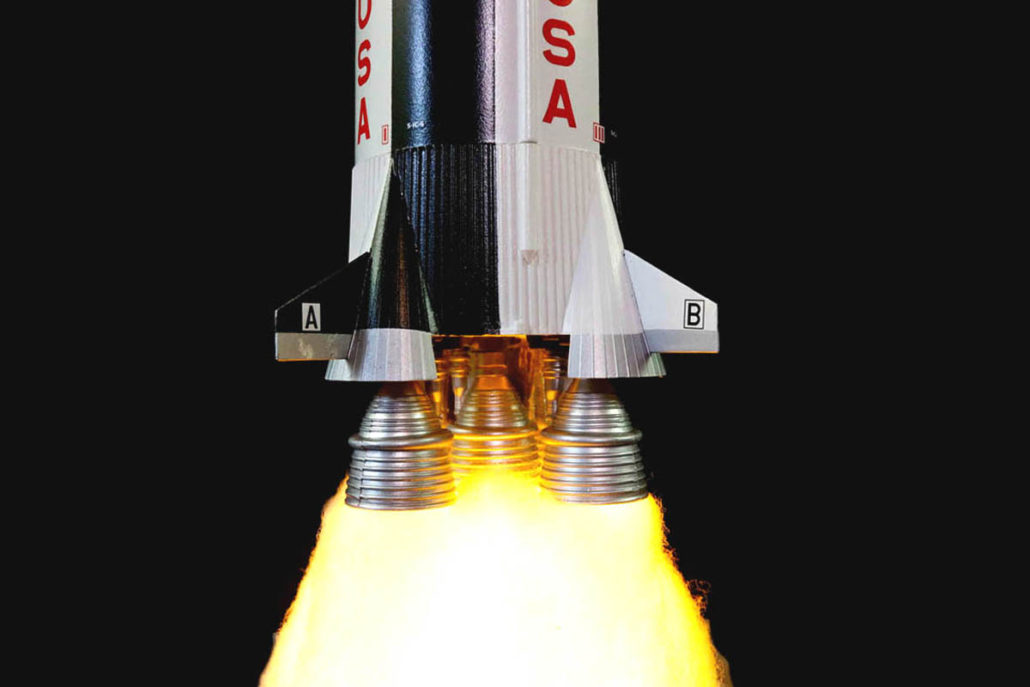
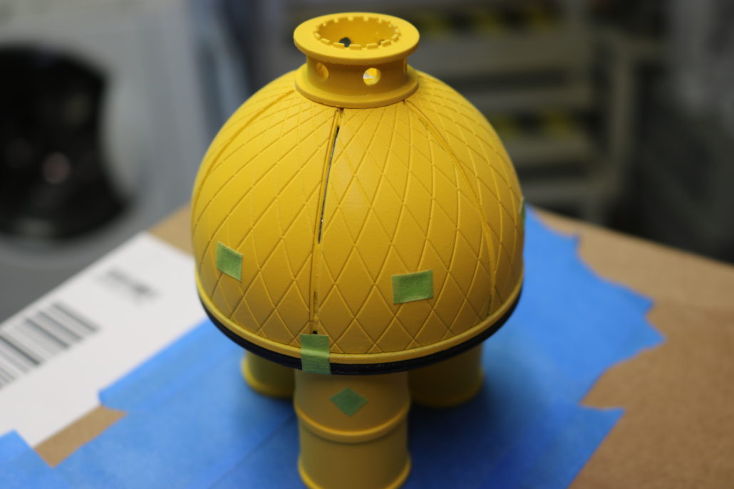
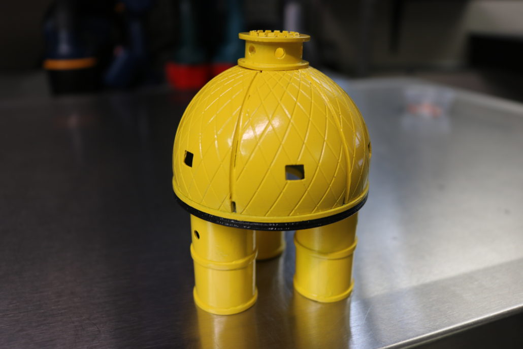
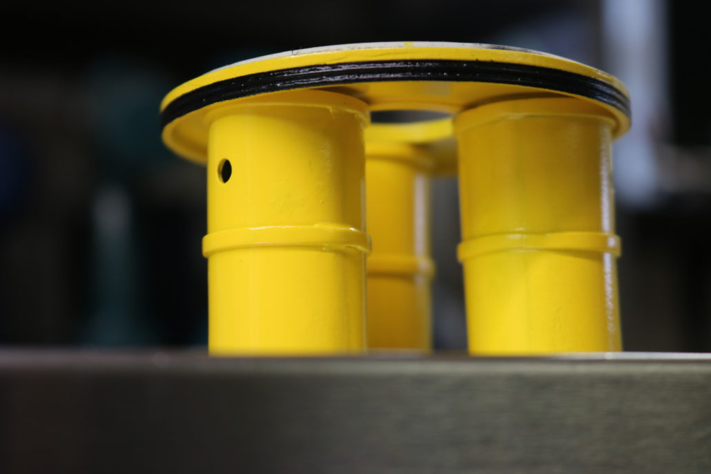
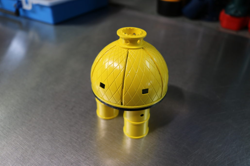
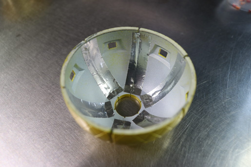
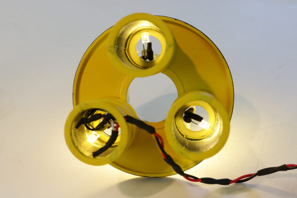
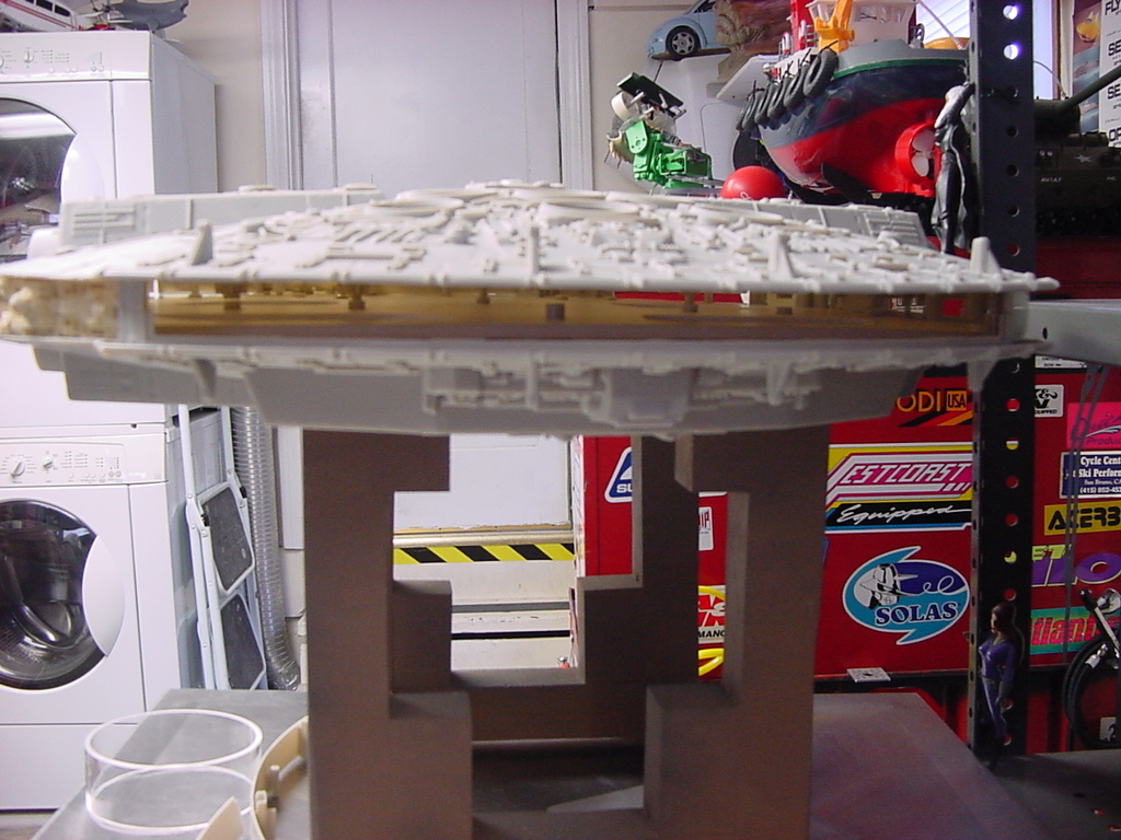
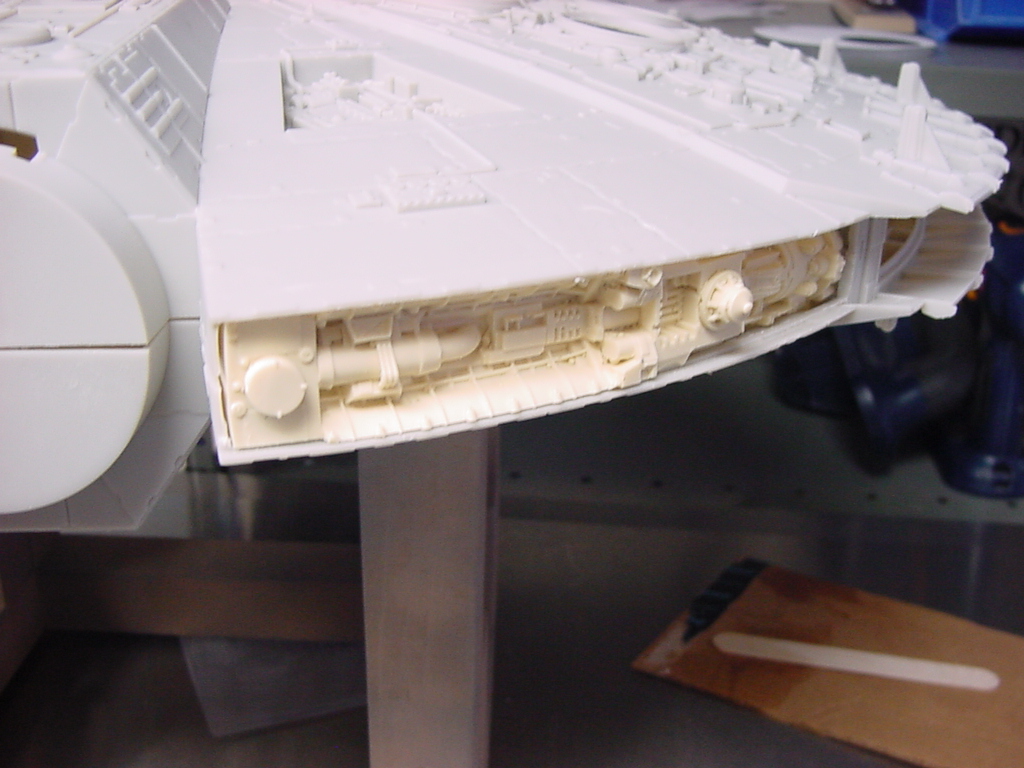
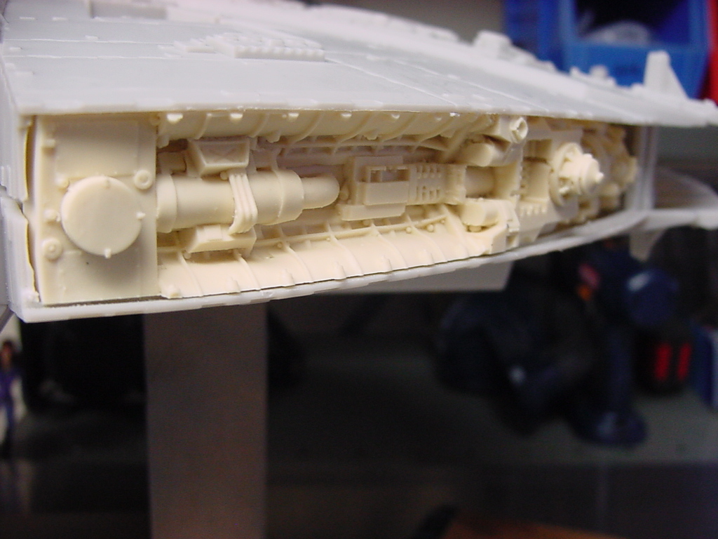
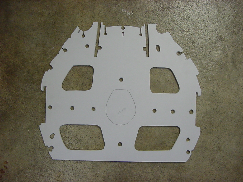
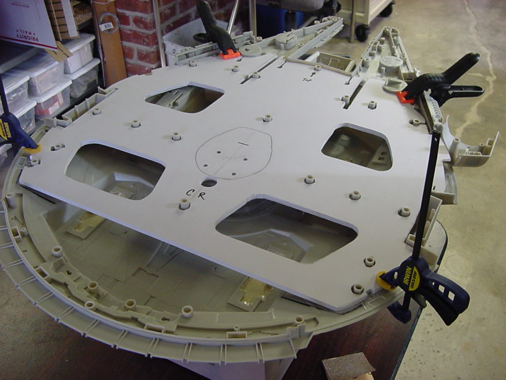
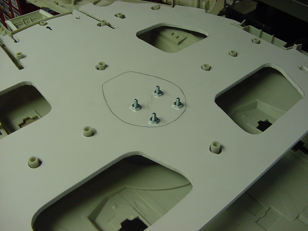
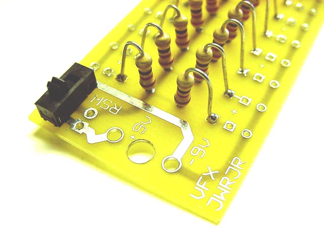
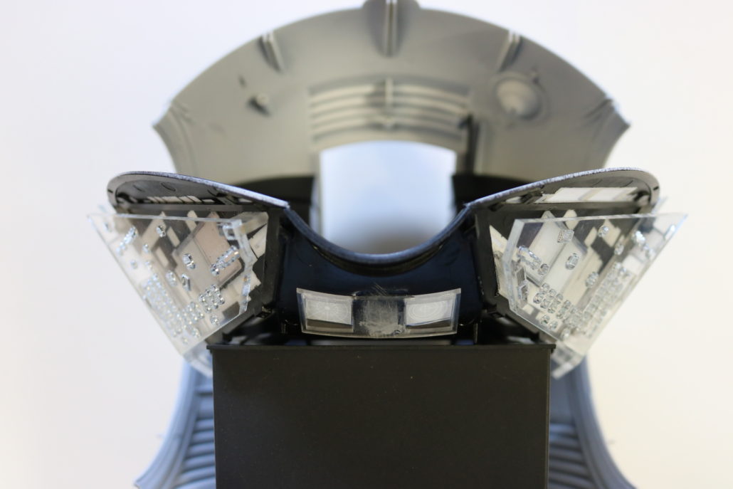
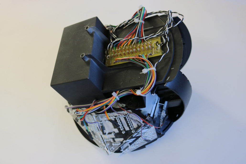
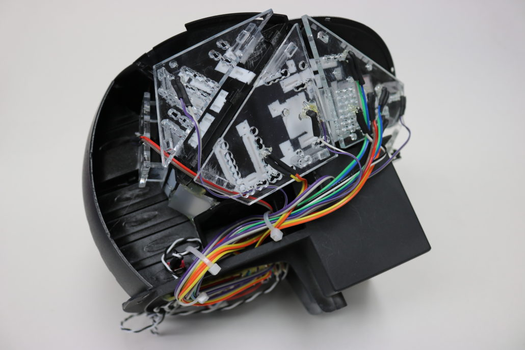
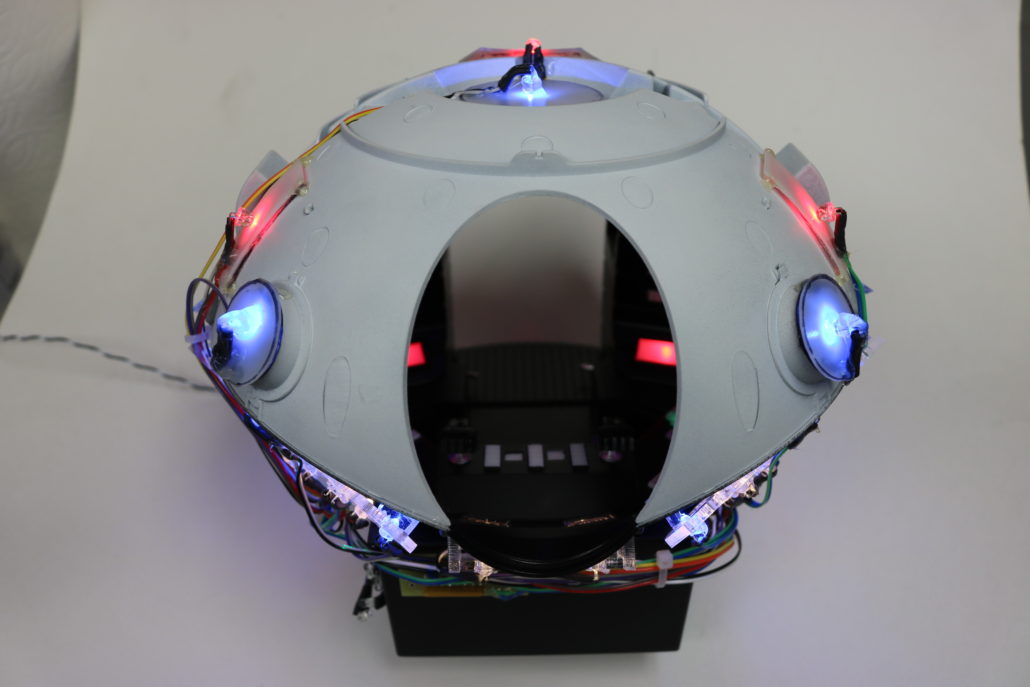
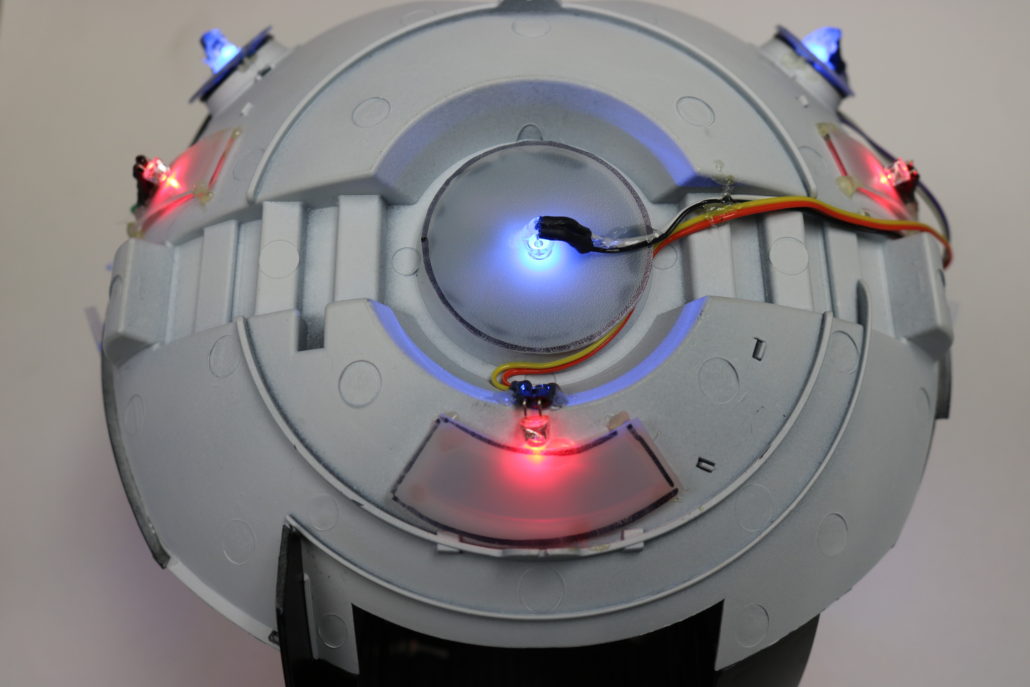
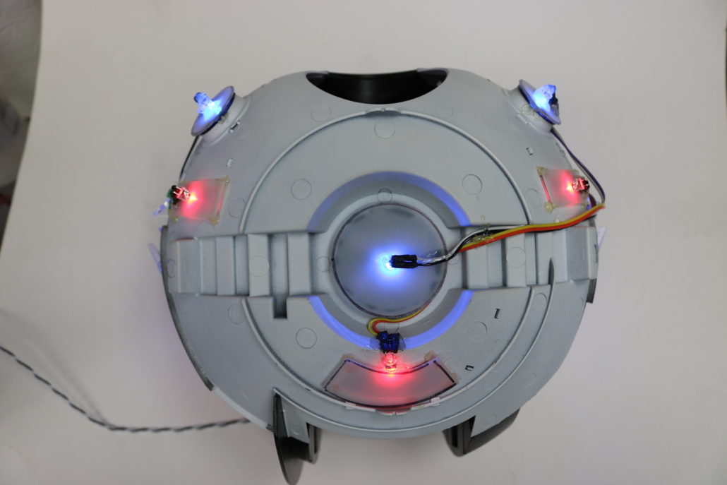
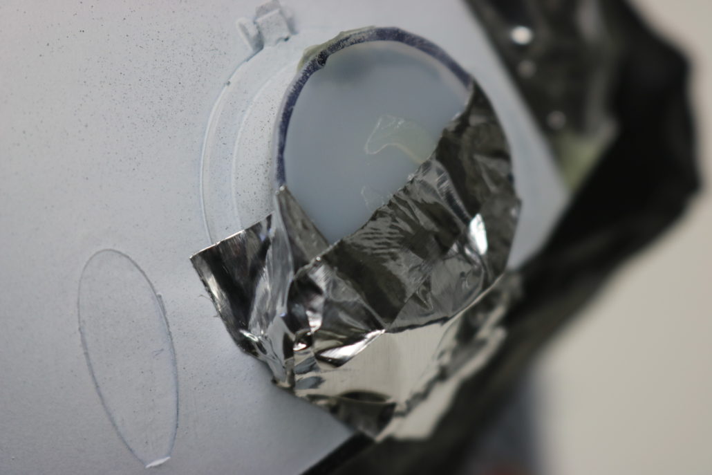
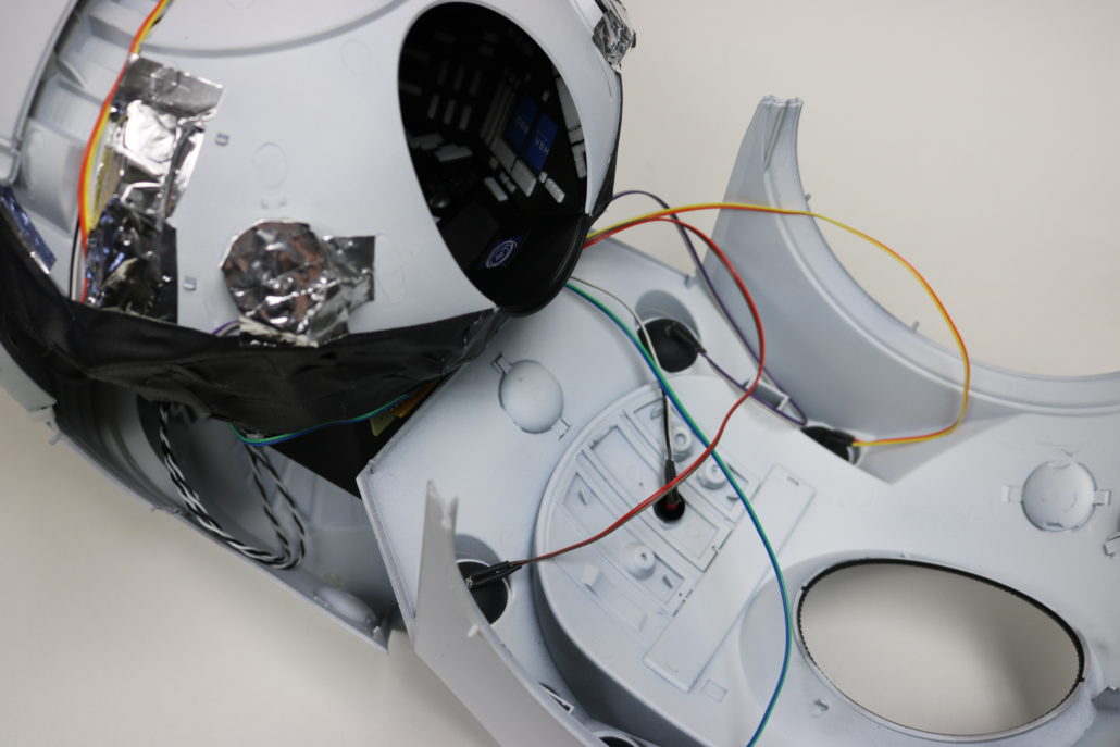
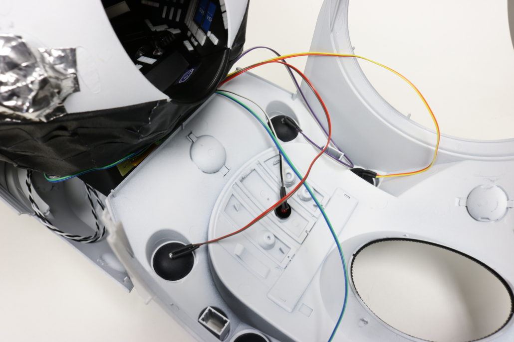
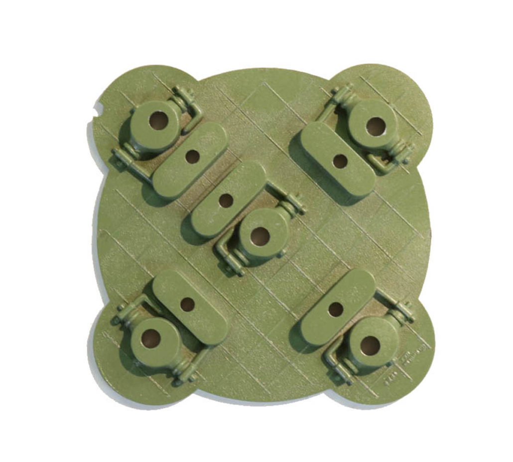
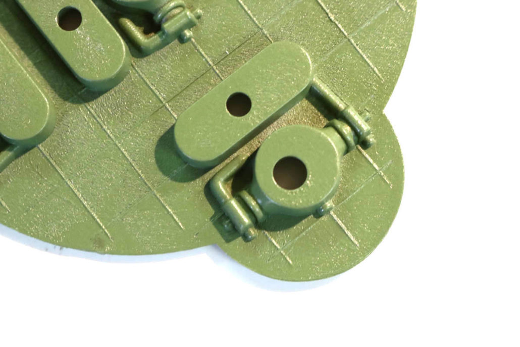
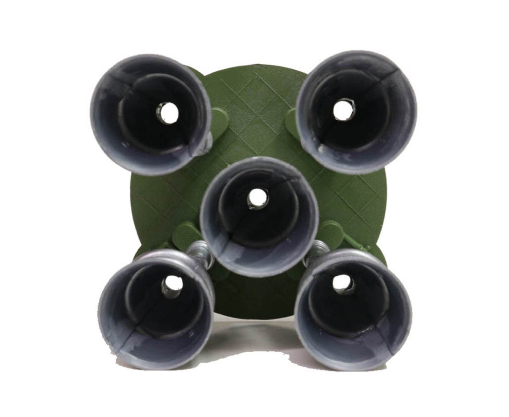
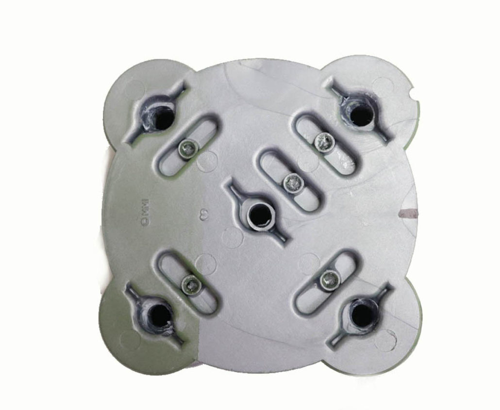
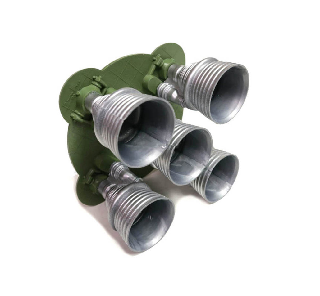
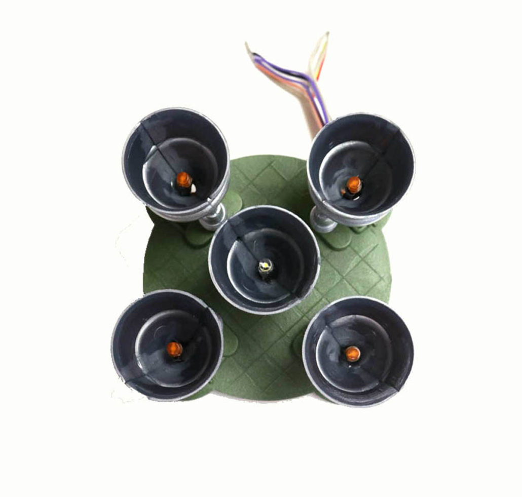
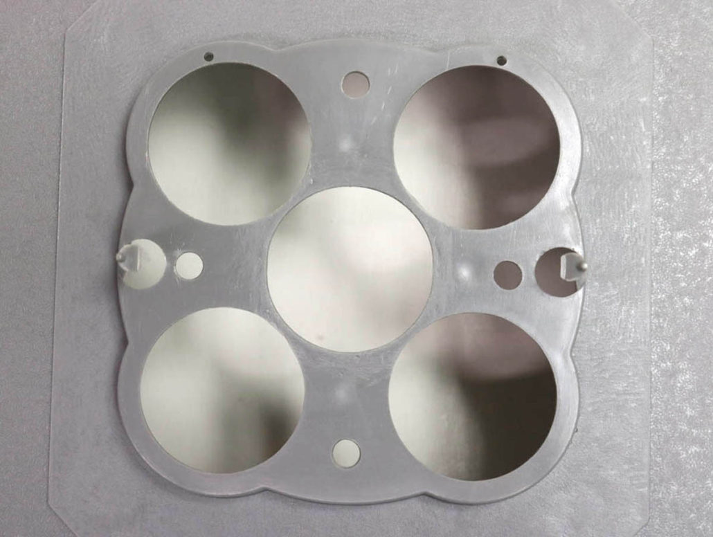
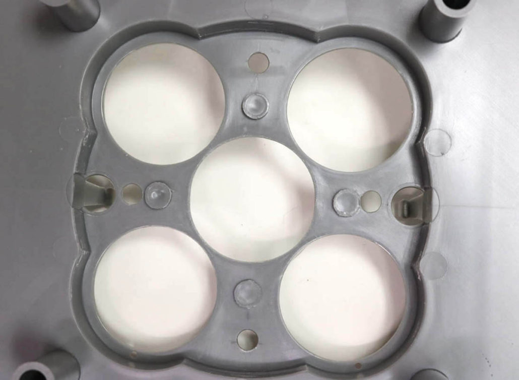
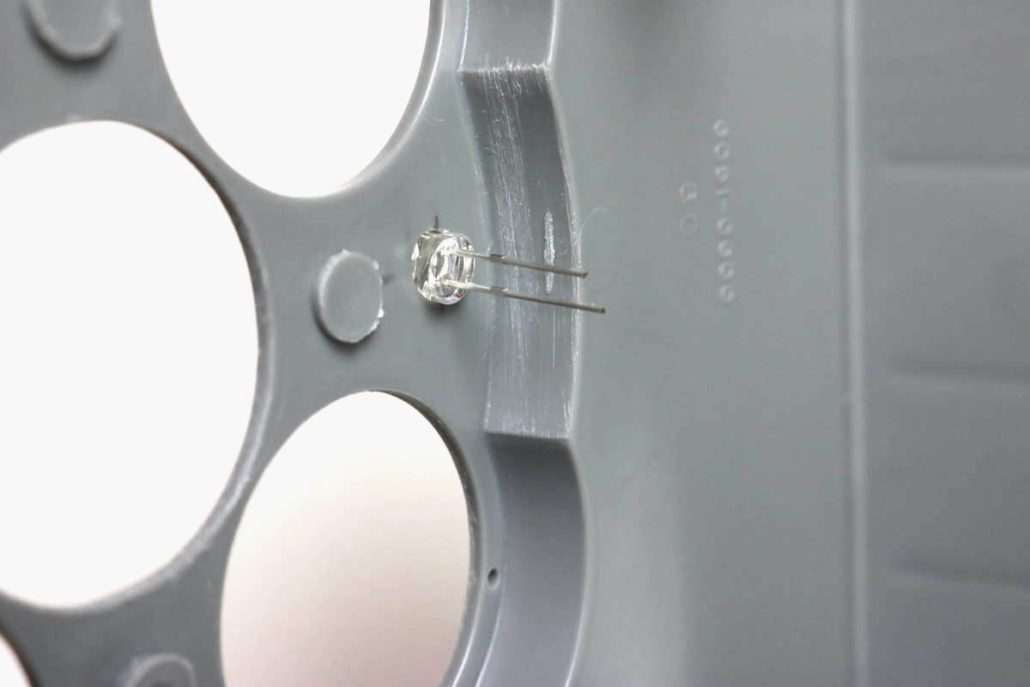
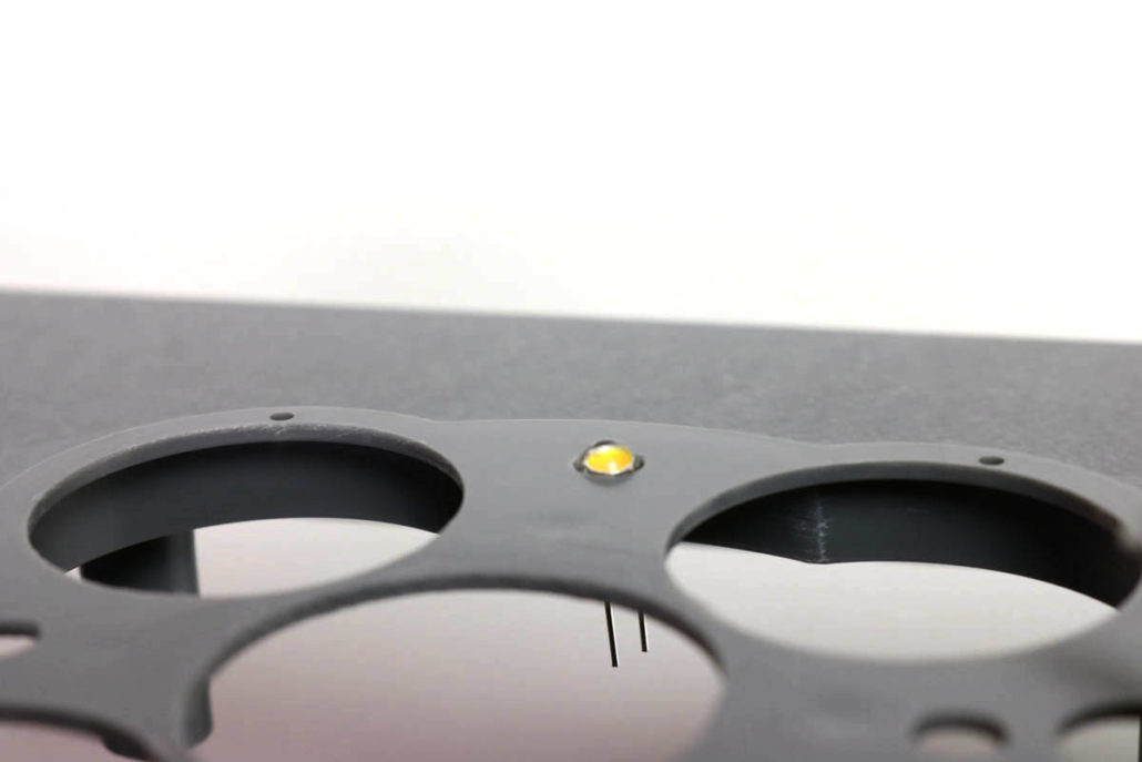
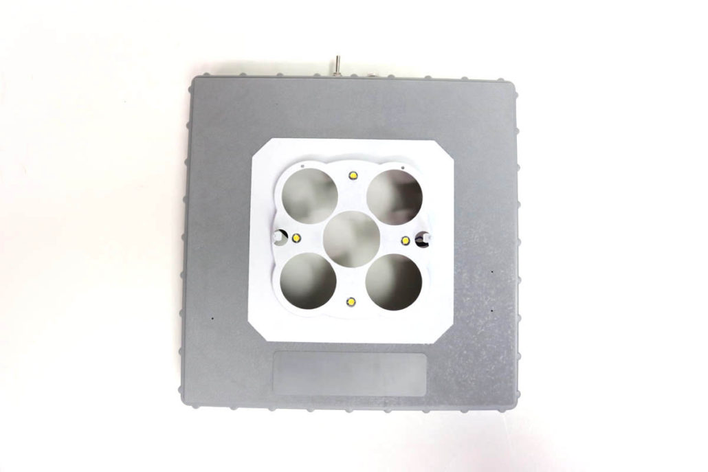
Start by opening the model and get your self familiar with the engine parts & the general structure of the kit. It is generally a good idea to have a plan of action drawn up to keep you on track, and note any lighting that will be added later in build. The main engine bulkhead support will need to be drilled out to accept wire & LED’s fed through the engine bells. There are 4 orange and 1 warm white LED’s dedicated for the engines. I used the 4 orange around the perimeter & the 1 warm white in the center to give more punch.

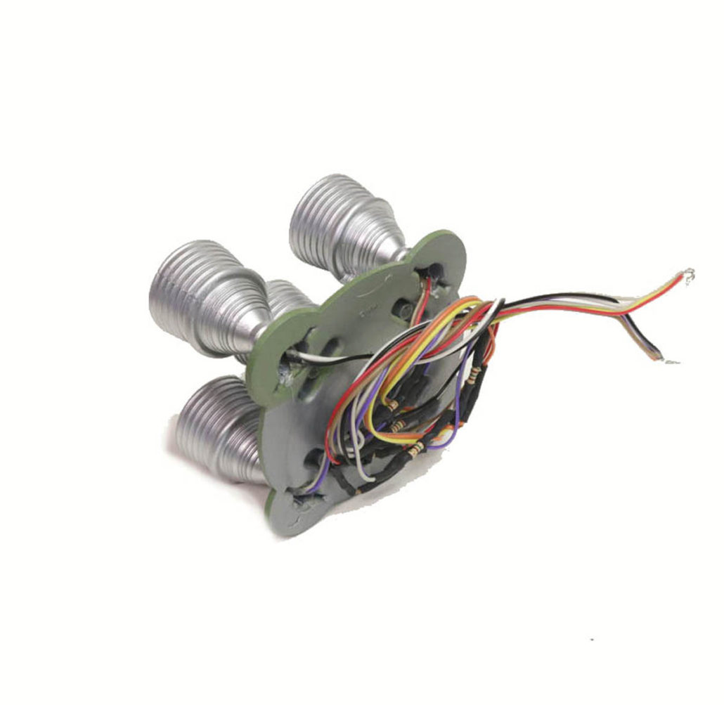
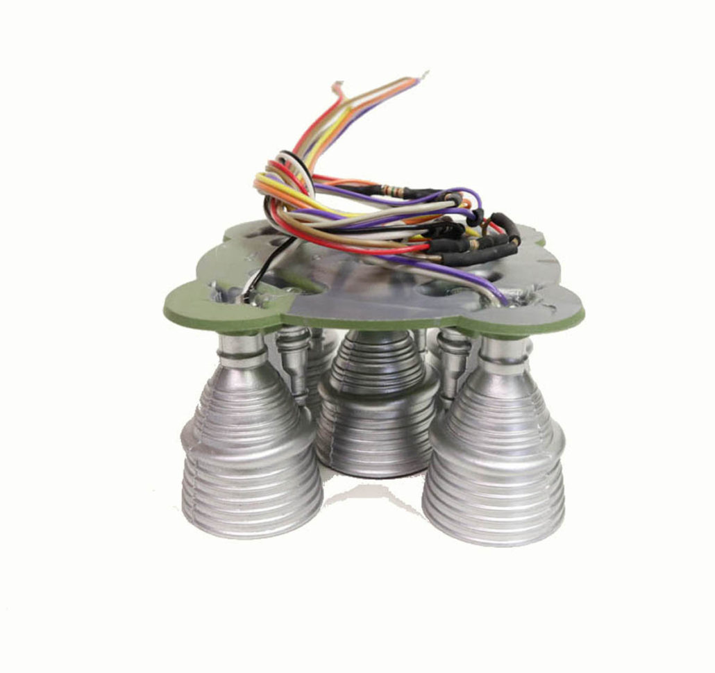
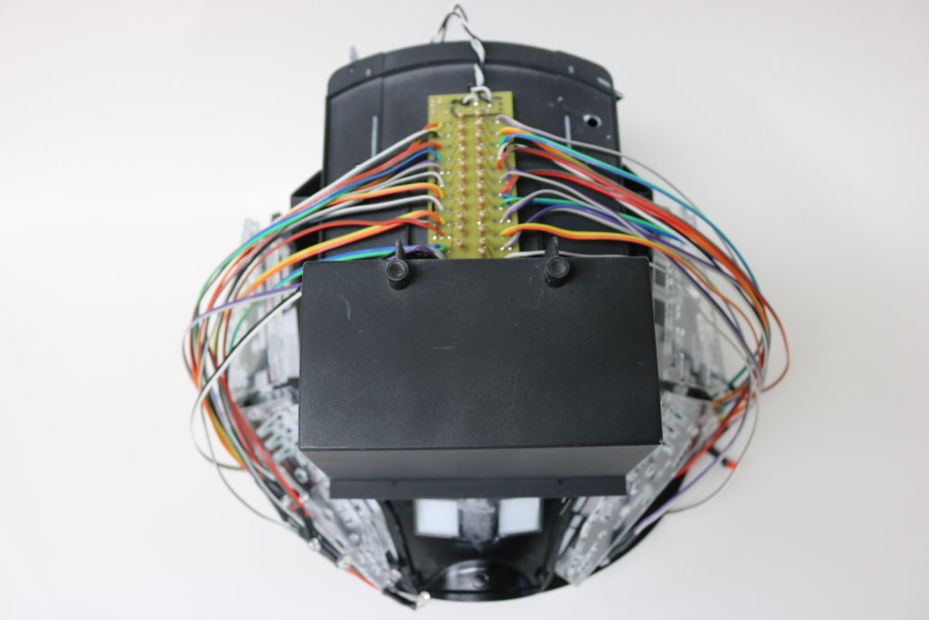
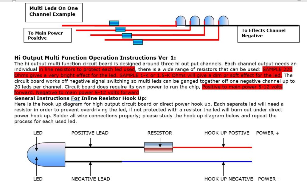
Regardless of what kit you’re using, the animated version is wired the same way as the static version. Both setups use a common technique which utilizes a film resistor to protect the LED from voltage damage. How this is done is by connecting an inline resistor on the positive side of each LED used… you will need to have one resistor for each LED used. All positive wires will come together and be connected to the male power, goes for the ground or negative wires. The animated version works the same but instead the negative leds wires will go to the effects channel coming for the circuit board. The board itself will need direct power.

WIRING DIAGRAM

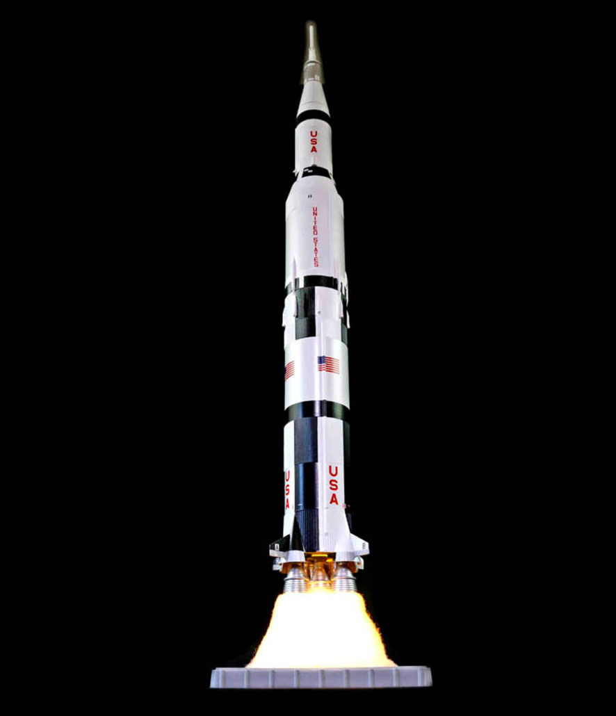
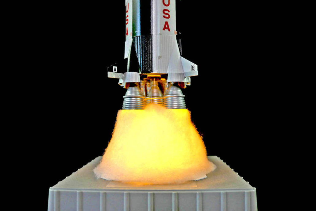
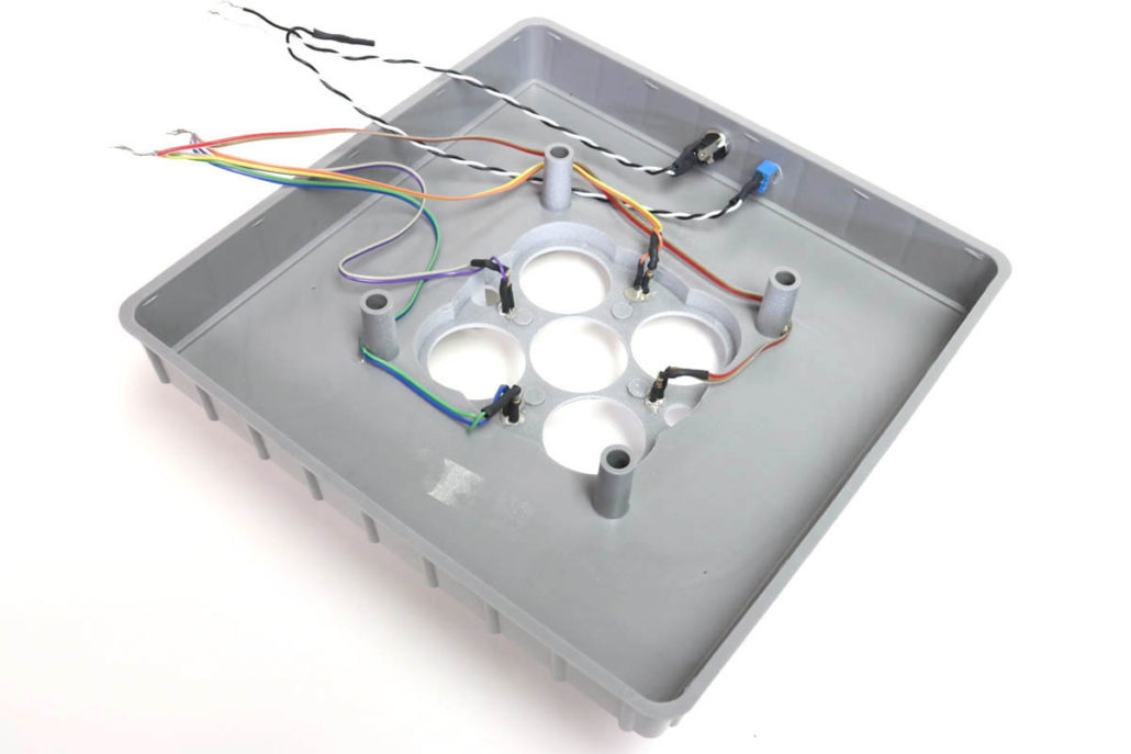
There is also base lights that will need to be drilled out. There are 4 yellow LED’s in the kit, which will be used for the base. I found it best place them midway around the engine exhaust holes, although they can be placed anywhere according to the builder’s preference. After pre building the LED’s with resistors and mounting them in place, I ran a small wire down to the base to power the LEDs. There will be a few sets of wires running from the rocket and the base, which will be hidden with the batting material when finished. I also used a 1 1/4″ clear plastic tube to elevate the rocket for more effect. All the battery & switching is mounted in the base.

Finally, before closing up and mounting the rocket, it is best to test run the lighting effects for a burn period of 6-8 hours (this will insure that the system is operating properly. The batting material can be placed in anyway that looks best for you build up. If you have any questions, please contact us direct with an email or call by phone.

Deep Sea Lab Project

Getting Ready:

The deep sea lab was a commissioned build up project that started in early 2020. The client wanted to have this as a standalone model supporting it’s own power supply for lighting. When the model kit was delivered, I was blown away at the quality of the kit! Paragrafix did an amazing job with this model – parts went together with very little effort and castings were clean & tight.

Lighting

I started by figuring out how I could get the best effect with the least amount of electronics. After running a few tests in the main interior and leg parts, it be came apparent I would need to use two different lights to get the right effect. In the main lab area I used a 1″ 1/4 clear plastic tube cut to fit around the inside ring. I used this tube to mount a section of DD W White 50/50 strip to handle the main lighting. Both the main floor and wall sections needed to be heavily blocked with paint – the three legs needed the same treatment to avoid light ‘leaking’ through at the seam. In the three leg areas, I used 3mm warm white LED’s bent 90 degrees to face inwards at the circle windows. I found that using a 220 ohm resistors in line with LED’s produced enough light to make the leg look presentable.

Battery Box & Base

The battery box as a standalone model does not look too bad, but in my opinion was a hideous eyesore on this build. As an easy fix, I painted & dressed up the battery box to look like parts of the lab. First, I taped the on/off switch and used vinyl promoter to get a good surface stick to the box. After, I dressed it with a few window decals & gave it a name, “ONCO”, which was improvised with a company sticker my good friend Fon Davis had given me (sorry buddy, it fit the scale and looked too cool not to utilize). For the final part of the build, I constructed the base with a piece of sintra cut in a smooth shape to lend more of a natural appearance. I then decorated with some homemade resin rocks & cliff wall facade for depth around the model. Finally I finished off the piece with some underwater greens & grays to emulate algae from the sea floor.

Finished

Hasbro Falcon Build Part 2

Getting Ready:

This next phase of the build was removing the side panel areas and pre pairing the parts for fit up. I started by first removing the entire engine area, the next was the rear engine port & starboard side panels. I then moved up to the main cockpit area & engine side detail, the last sections where the front mandible headlight sections. Its best to have the aftermarket parts in hand before you start the cut out, this gives you a much better understanding of how they will be placed into the openings.

Falcon Build
Engine Area Cut Out
Falcon Build
Engine Side Cut Out & Fit
Falcon Build
Side Engine Part Almost Fit

The next stage in the build was to make a mid plate to support all the aftermarket replacement side panels. This mid support plate will give a gluing edge to mount the side parts and better support the front mandibles. I used a piece of Sentra to cut the pattern out, it’s light weight, ridged and perfect for this application. Once you have test fitted the inner plate, make sure that is not hanging up the model half’s from closing. I used 30 minute epoxy here & there to tack it down. It does not like to stick to the model plastic very well, but when all the parts are glued on it seems to hold. I am also incorporating a hard mount through the base. I will go over in the next post.

Flacon mid plate
Mid Plate Support
Hasbro Falcon Build
Mid Plate Mounted
Hasbro Falcon
Stand Mount Bolt Up

2001 EVA Pod Build Part 2

Getting Ready:

Headlights & Hal 9000: After you have fit the interior in the back half of the shell you’re getting ready to close up the front section of the model. There are two main areas that need to be set up for lighting.

Main Front Lighting

The front head lights or search lights consist of 4 light buckets. These light buckets will require a small 3mm holes drilled through the center of the back of the bucket shell. The ones I used in the test build where body white but the production kits come chrome plated, so with this said It might be better to drill the from the inside of the shell to avoid chipping of the chrome plated finish. Once you have a pre drilled the buckets you’re ready for mounting the leds in place, it is very important that you center the led as close to center of the bucket to avoid the google eye effect.

Bucket Drill Out
Bucket Front Side
Bucket Front Side
Head Light Mounted
Head Light Mounted

Hal 9000 Light: The Hal 9000 light is very straight forward but I must point out a few things to keep in mind. In the kit there is a small red diffused led, it is very important that you use the 2-K resistor in the kit, this will make the light look dim. If you don’t have the Yaymonsters add on kit, you will need to cut a thin piece of styrene to back the led. The styrene will need to be painted black for light blocking & screen accuracy as well. Another thing to keep in mind before mounting the led is to get it dead center of the Hal 9000 bay, if it is set off to one side or another it will look very bad on the finished model build. Again test all lighting before closing any main sections.

Hal Backing Hole
Finished Hal 9000 Light

In Closing Notes: I cant stress the amazing quality & craftmanship that went into the design of this model kit. As always if there is more detailed questions regarding the lighting & build of this model its best to contact me via phone call direct. Long emails back & forth never seem to work, so its best to drop me a call. Thanks for all your support of VoodooFX / Randy Neubert.

2001 EVA Pod Build Part 1

Getting Ready:

Building & lighting the new 1:8 scale EVA Pod from Pegasus Hobbies & Moebius Models. I received a test shot of this model and was blown away at the scale & design elements of this kit. As usual Moebius Models & Pegasus Hobbies have created a amazingly accurate model kit with enough room to fit electronics in it. I started by braking down the bulk body parts & getting myself familiar how the model fits together. In most test shots there are no instructions or decals with prototypes and sometimes it might be missing a few parts here & there. In that case, the model was pretty straight forward and all the main parts were in the kit. However, I did make some mistakes here & there. Lets get started with the lighting, once I had all the interior panels figured out where they fit I had to address the problem of the button lights. The first idea was to tryout bulk strip lighting , which did not work. The second try was using a wide angle led, this had some good qualities but again, had a washed out effect. So I then tried out a 3mm led for the buttons & it gave the desired overall effect. Note: VoodooFX has no control over third party aftermarket parts & accessories availability.

Yaymonsters Decal Kit

Using Aftermarket Parts:

Button Masking
Button Masking

Mounting Led Supports: After pre light blocking & installing the vinyl overlays I was ready to starting build the interior. Once the interior was assembled I made any touch ups at this point & was ready to move on to the acrylic support for the led install. The lighting support are ideal for lighting this model, I pre built the supports by using a small amount of acrylic glue. Using the stand offs “T & L” provided in the kit. Scuff the areas on the back side of the panels to mount the supports, you can us a small amount of CA glue for mounting.

Mounted Led Support

Circuit board & Leds: Most of all the electronics can be prebuilt outside the model & fit up to the interior before installing into the main body. I always start by building up the board first, this is done by soldering all the resistors on board & making any power leads or switching set ups. Now by taking some crude measurements at where I want to mount the circuit boards & where your leds are going to be mounted I start prefabbing the pre cut wire lengths to the leds. Once I have a few on the board I test the circuit to make sure its working properly. NOTE: I found it’s better to mount the circuit boards on the bottom of the back half of the main shell (this is a better location then the interior bench).

Premade Electronics Mounted
Lighting Test
24 Port Driver Board Close Up
24 Port Driver Board

Main Interior Mounting: After all the led lighting is mounted in desired locations I suggest to run a short burn in test. A burn in test is where you run the lighting for a few intervals, I start by running it for 10 minutes & rest for 10 minutes, then run it for a 30 minutes & rest for a 60 minutes. After you have done these tested the chances of a burned out led or a loose connection will show itself in the burn in period. Another good suggestion, is when performing these tested is to lightly tug the wiring here & there to insure the connections are tight. (a loose connection can come back to haunt you when the model is all closed up.) I will go into detail regarding the front head lights & Hal 9000 lighting in part 2. As always any detailed questions can be best answered by contacting me directly by phone.

Interior Installed In Back Half Of Model
Side View Interior Mounted

BUILD GALLERY

Hasbro Falcon Build

Getting Ready:

I just started a Hasbro Falcon conversion & want to share the build process. I am using a few different aftermarket kits to make the model more studio like and will be putting up links to the parts & companies. I hoping to show case many new model build projects on this page, so please share with your friends & check out the blog frequently.

I used the Randy Cooper side replacement kit & the YayMonsters panel kit as well, and a few parts from Shapeways & cockpit replacement from 3D Falcon Parts. The next step is to remove the areas where the new aftermarket parts will fit.

RC After Market Parts
Randy Cooper Parts

Its best to already have the parts in hand so you can get any idea of how the parts are going to fit. First unscrew all the screws form the model & split the model in half, this will give you access to remove the panel areas easily.

Hasbro Falcon Conversion
Model Opened Up

I did start with removing the landing gear pads first, since this build up was going to be in flight. This is a tricky thing to cut out areas that will be replaced, I used a razor knife and almost cut my thumb off, so please use a right angle cut off wheel and take your time removing these areas.

Hasbro Falcon Conversion
Stock Landing Gear
Falcon Conversion
Landing Gear Removed