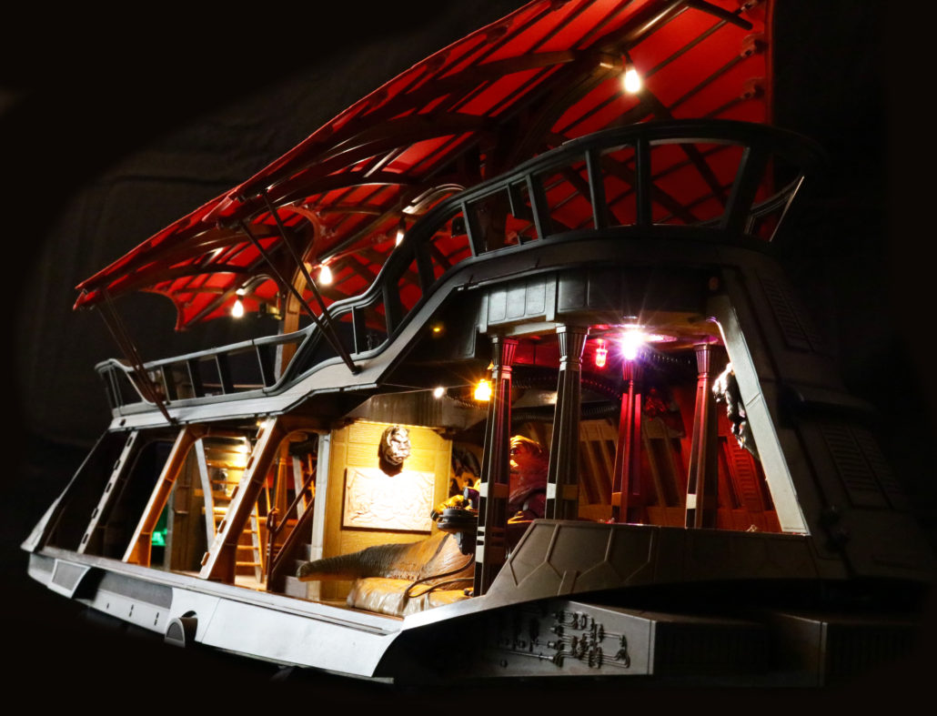
Blade Runner 2049 Spinner
Getting Ready:
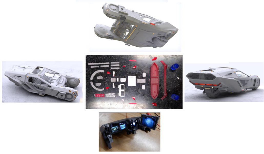
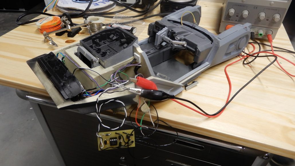
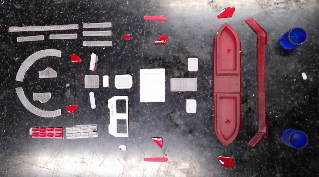
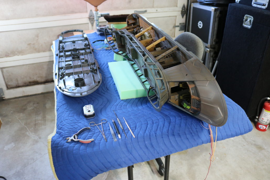
In this blog we’ll be going over the lighting kit instructions for Randy Cooper’s 1/12 scale 2049 spinner car from Blade Runner. First, unpack the electronic parts kit, read all documentation, and study the diagrams. Its also good practice to have your own research material prepared before starting the lighting process. Begin by reviewing all the model kit parts… getting a general idea of how the model comes together. We’ll be breaking down this model into three categories: lighting – strip lighting – effects lighting.
Circuit Board Info
This kit comes with two circuit boards, one is for general on lighting & the other is strobe & thruster effects. I have added some diagrams regarding the layout of the circuits to get a better understanding of the electronic.

ON LIGHTING:
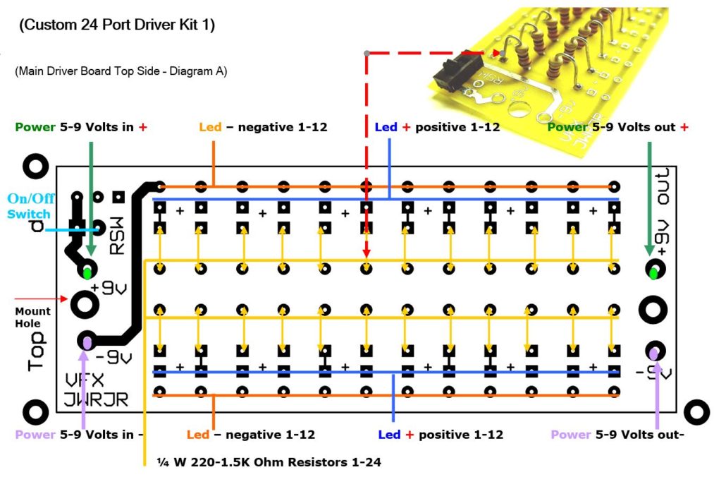
In the kit is a 24-port driver board which will be used for some of the on-lighting features. When using this configuration, you have the choice of what resistor to choose from, and the different output levels for each LED. Using the 220-Ohm resistor will give the brightest output within a safe operating range. Using the 1.5K Ohm resistor will produce a dimmer output, giving the LED a much softer effect. All other LED’s will use the in-line resistor set up, as displayed in the diagram above.
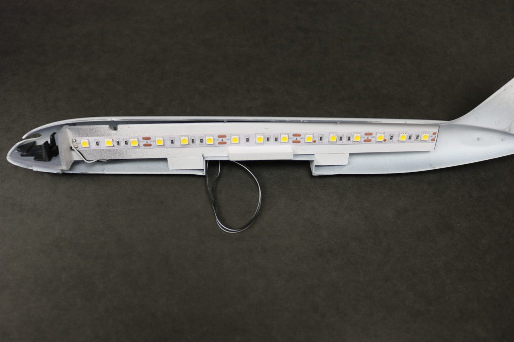
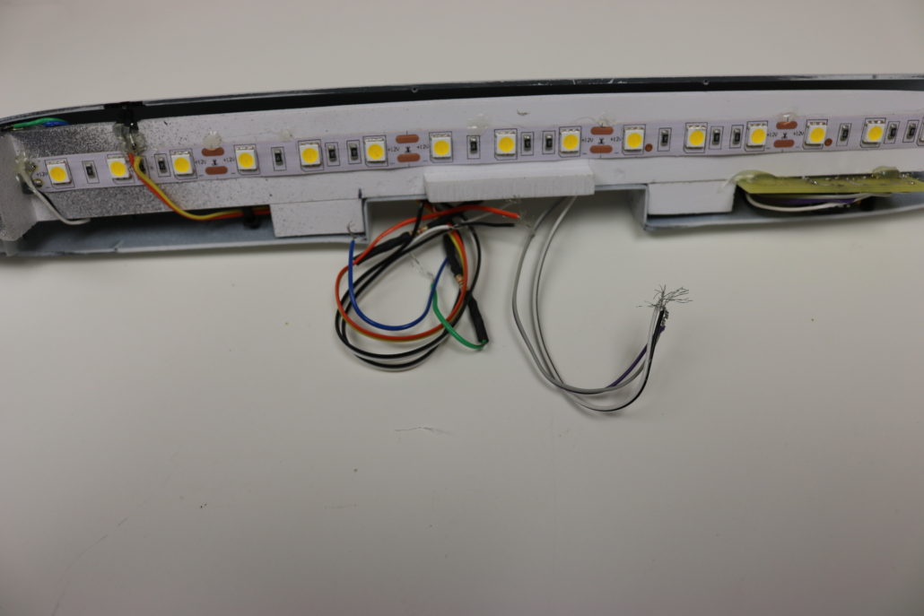
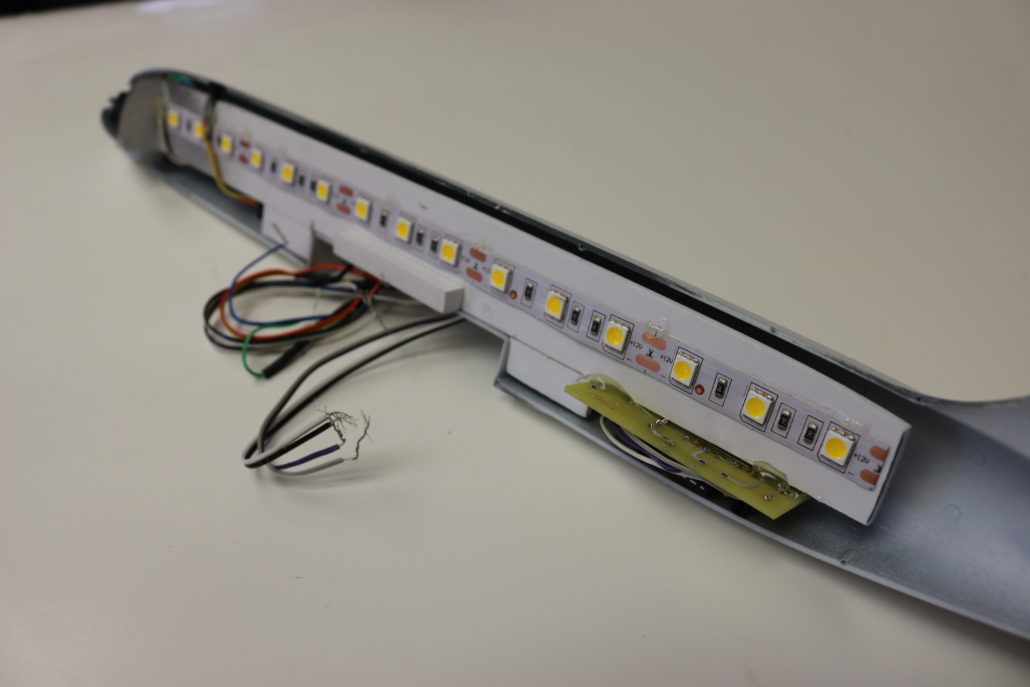
STRIP LIGHTING:
There are three different types of strip.
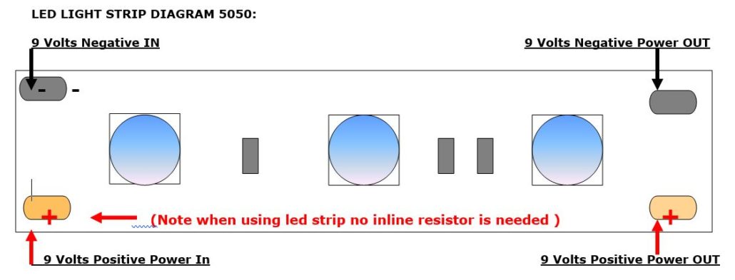
50/50 Red Large LED’s this will be used for the main rear engine.
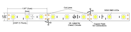
0805 Red Micro Strip this will be used for the lower rear engine slot.

0805 White Micro Strip – this will be used for the light bars around the doors & main flood light bar in front.
Cut strip to fit these areas. NOTE the Strip can only be cut in 1” sections or every three LED’s.
When connecting the main positive & negative power wires to the strip, no inline resistor is used.
NOTE: When using the 0805 micro strip, the positive & negative hook-up pads are on the back side of strip. You will need to make the connection points at either end of the strip… if you try to hook them up in the middle of the strip, it will not work. You will need to also scratch off the clear coating on the pad with a hobby knife or blade. When getting ready to solder, do not try to hold the wire on the pad & solder at the same time. When the pad is prepared, solder two small balls to the strip pads first, then pre-tin the wire ends. Carefully solder one wire at a time to the solder ball, you should not have to re-apply more solder to the connection point. Make sure not to cross wire leads over the pads. All positive & negative LED’s can be ganged to one central point, and then be hooked to the main power along the buildup.

EFFECTS LIGHTING:
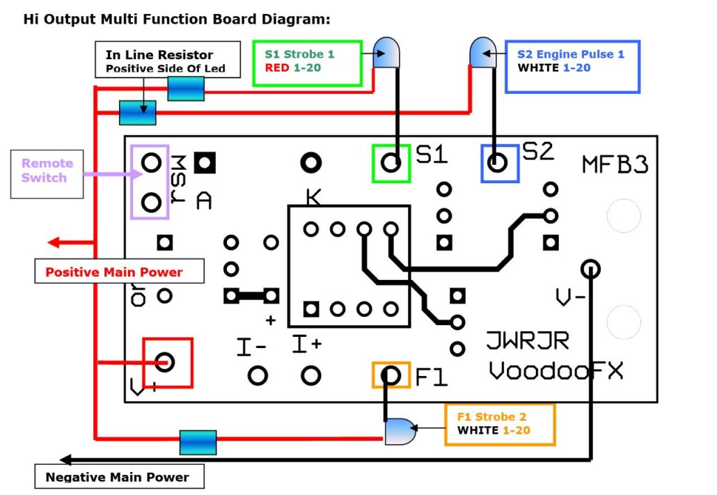
In the kit there is an effects circuit board, this will control the double strobe & engine pulse feature. The circuit is based on a high output channel function, meaning you will need to add an inline resistor for each LED (Please refer to the diagram above). It is best to wire the resistor to the LED on the positive side of the lead, and return all positives back to main side of power. The negative side will be hooked up to the effects board (Marked S1 S2 F1). The circuit board itself will also need power, to do this connect the positive & negative board wires to the main power hook up.
EFFECTS CHANNELS:
S1=Strobe effect 1 negative wire (RED TOP STROBE)
S2=Engine effect 0 negative wire (WHITE BOTTOM THRUSTER)
F1=Strobe effect 2 negative wire (WHITE BOTTOM STROBE)
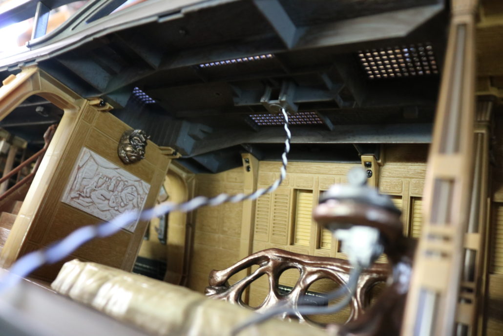
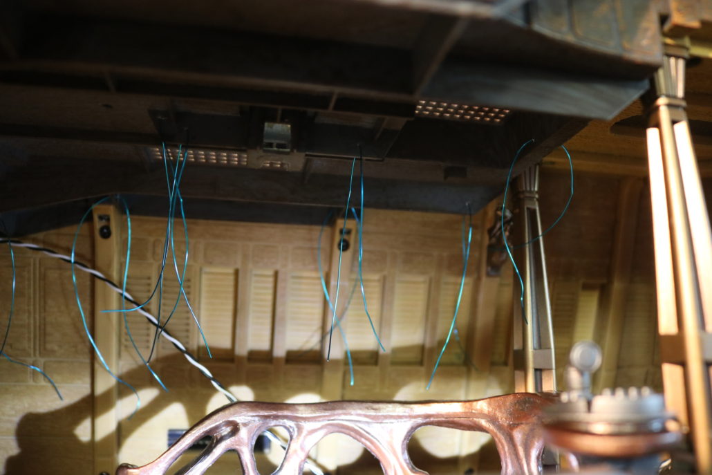
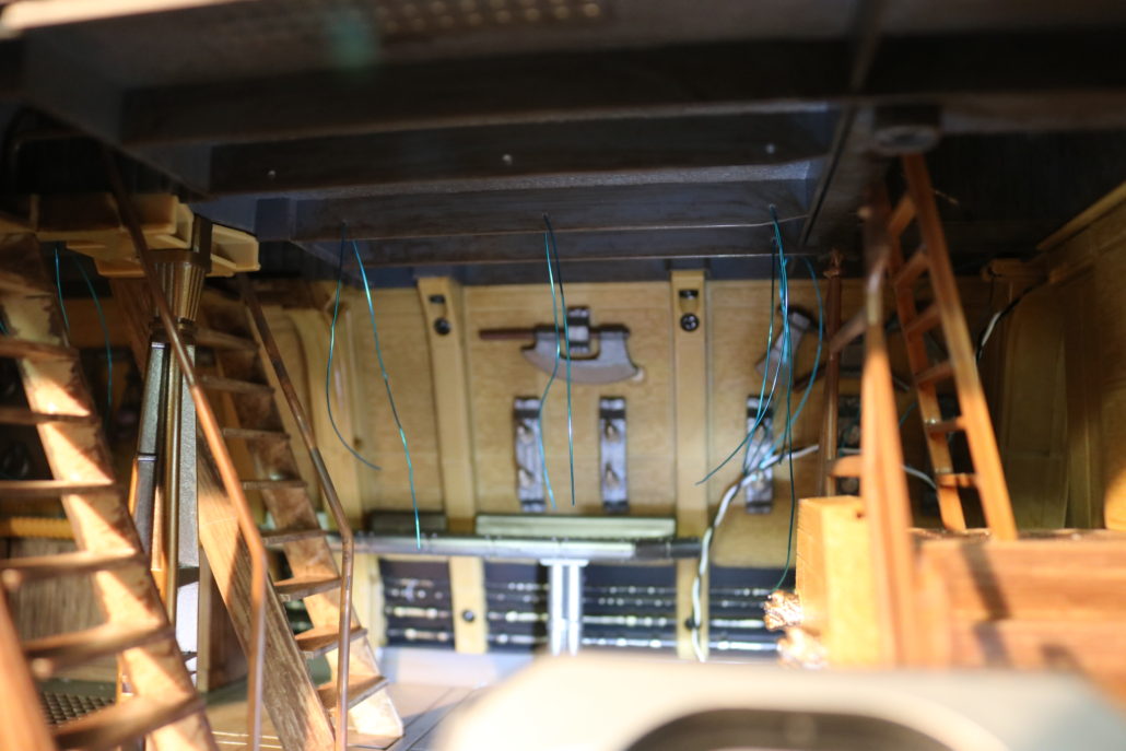
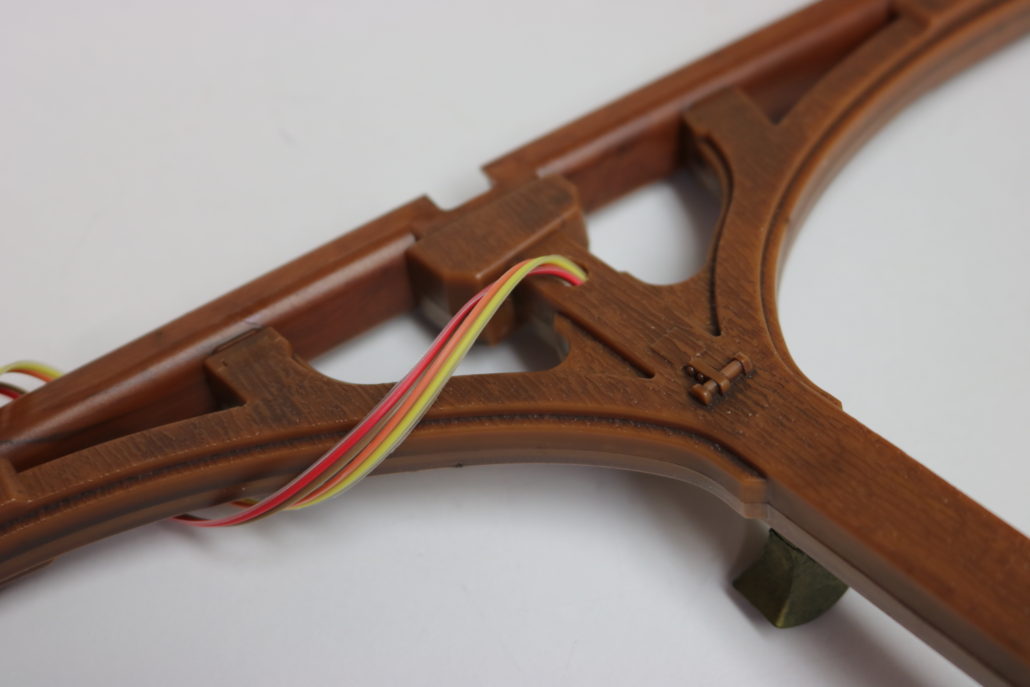
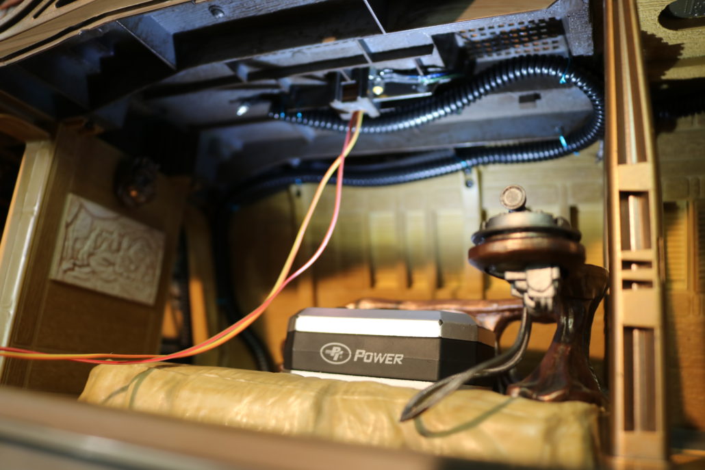
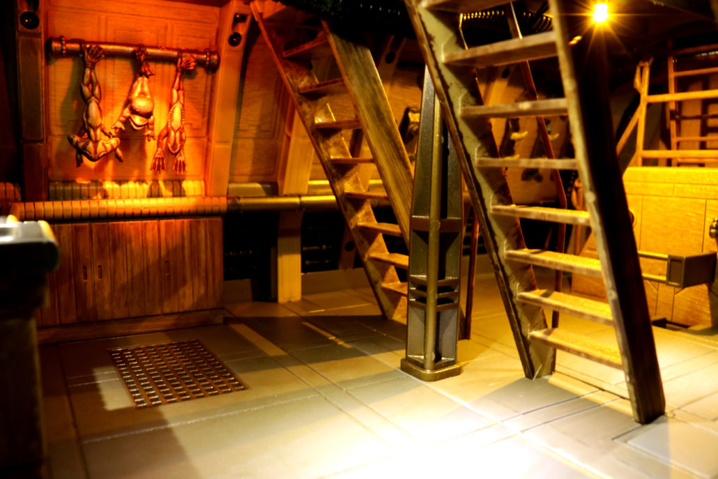
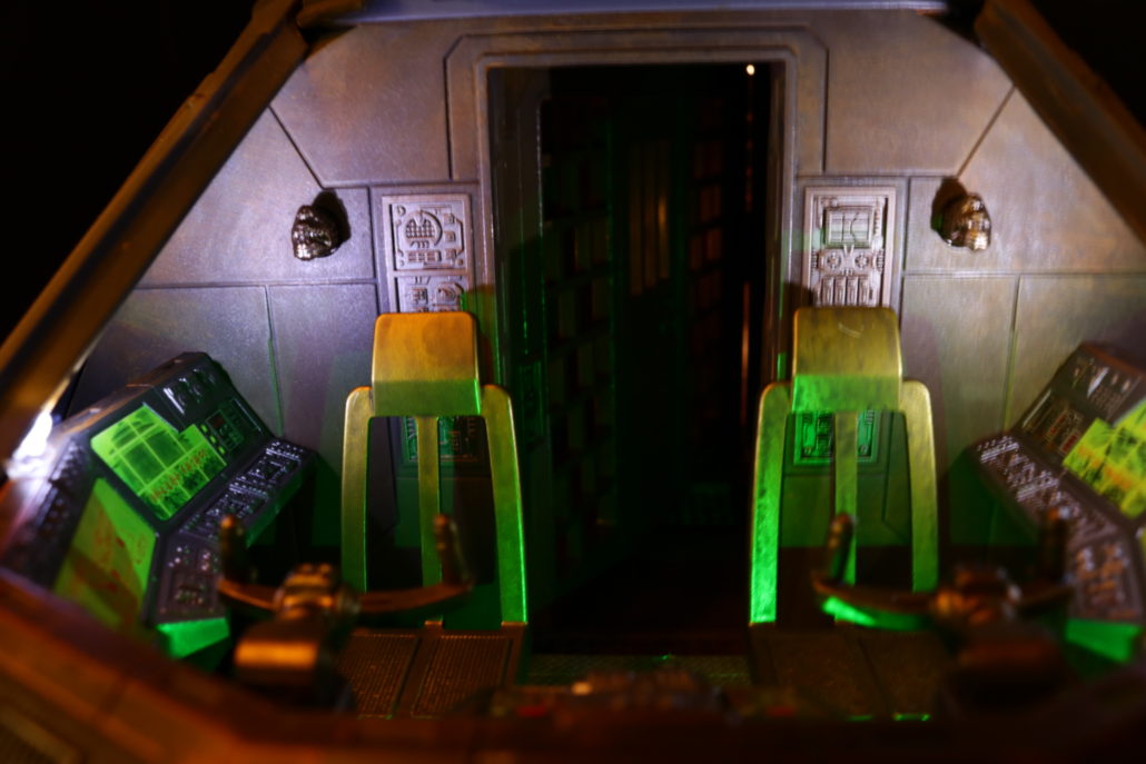
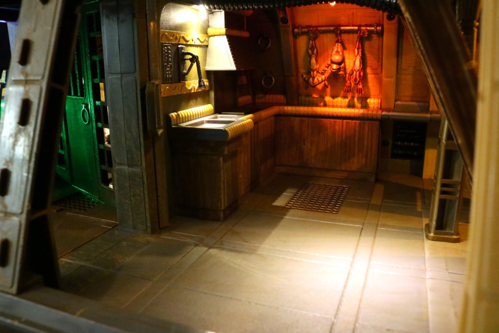
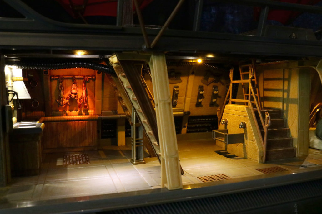
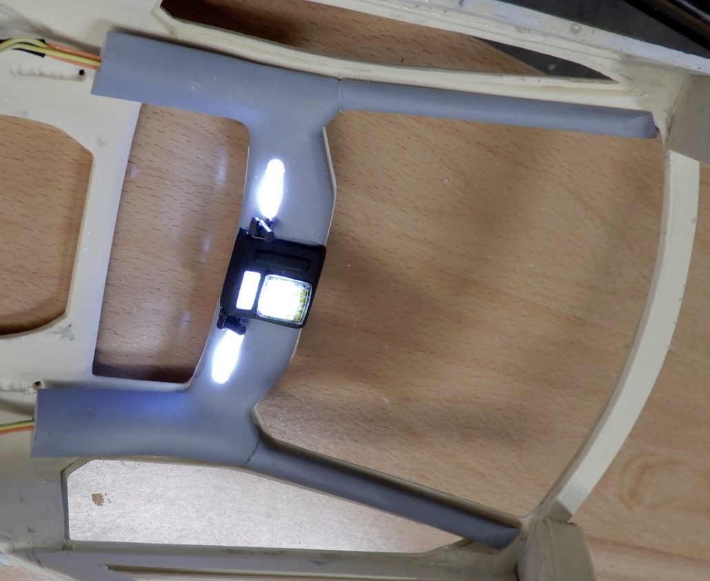
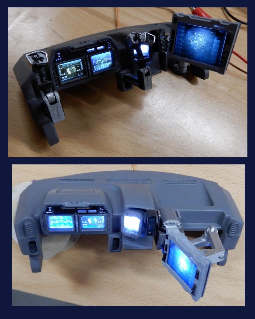
Interior
The interior is one of the first areas that can be almost completely pre-built, painted and lit.
The large main monitor X-1 W 4.7mm large bookend style LED. Use 220-ohm resistors.
The smaller main monitor X-1 W 4.3mm small bookend style led. Again, use 220 ohm resistors.
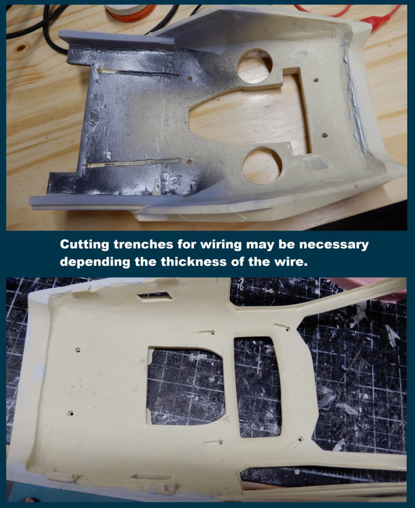
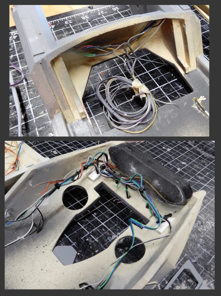
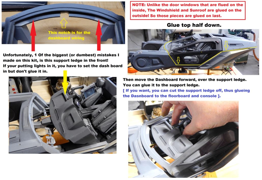
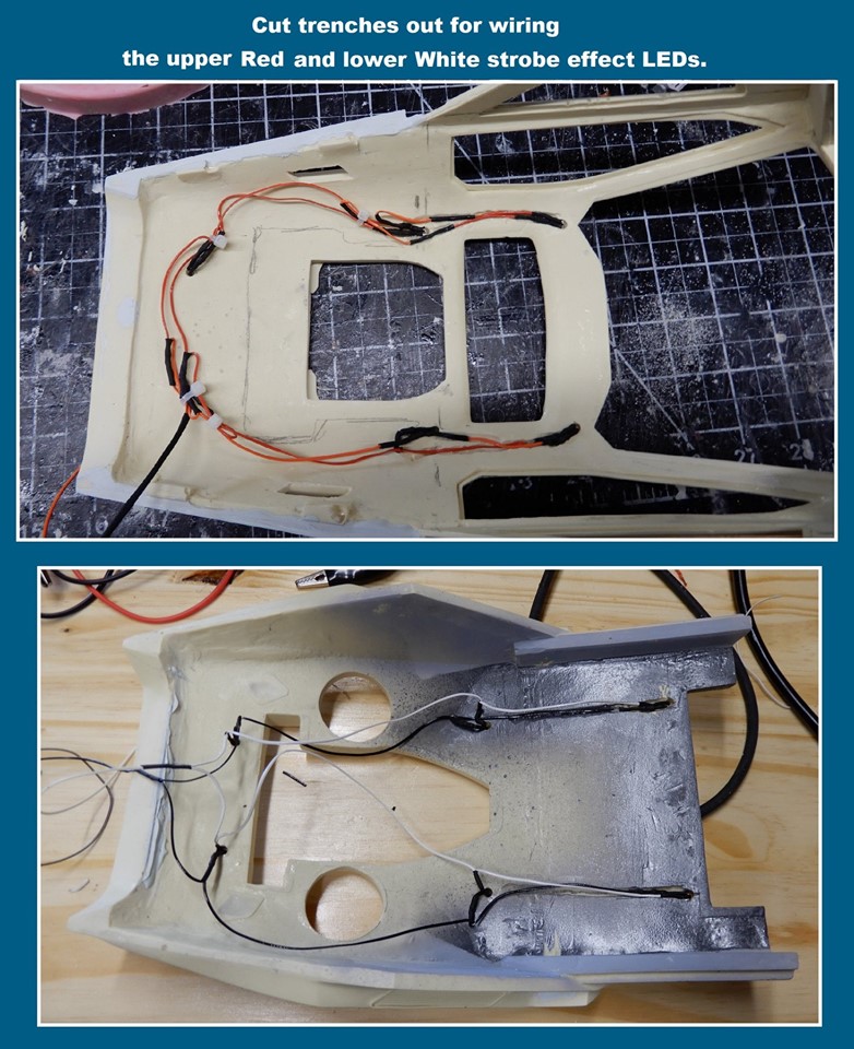
All other dash boards, consoles, overhead console & back seat wall use the W 3.0mm leds. Use the 1.5K ohm resistor for all the areas above. You will need to make some modifications to the upper roof section by cutting in various trenches to lay the wiring in.
The door in side panel accent X-2 Y 3.0mm standard led for these areas. Use 1.5K ohm resistor.
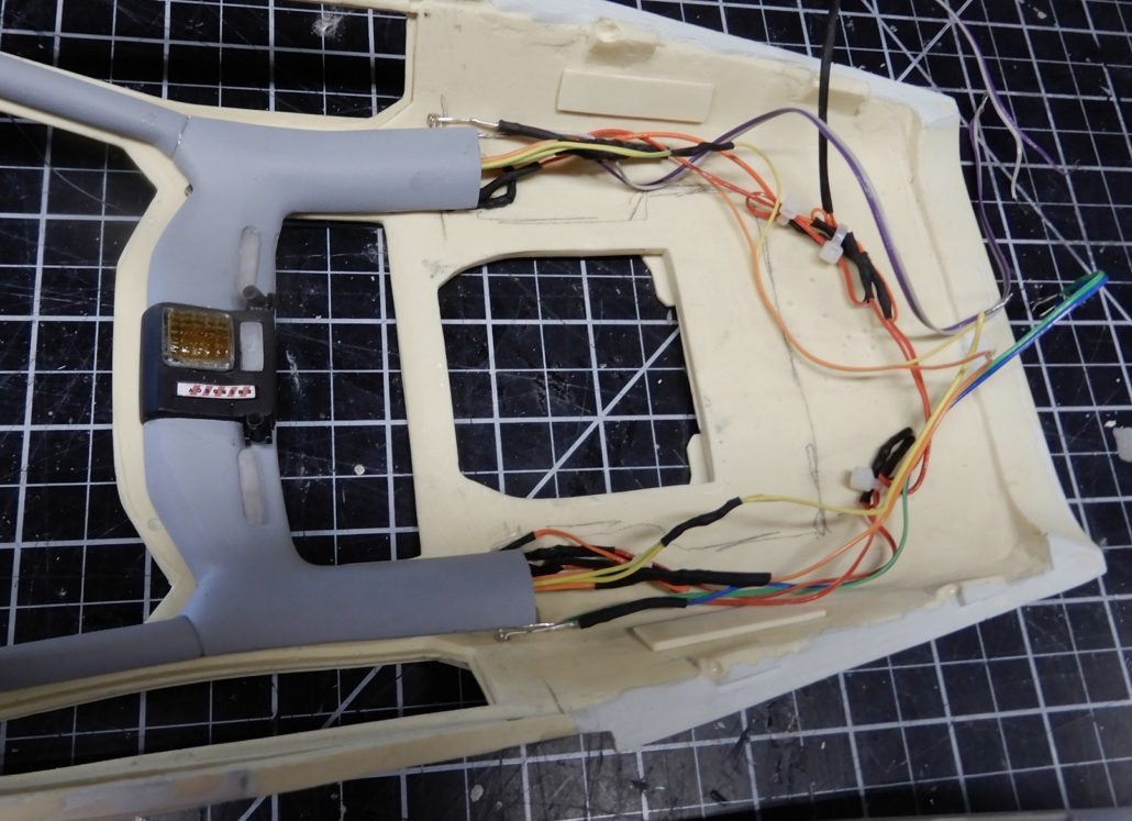
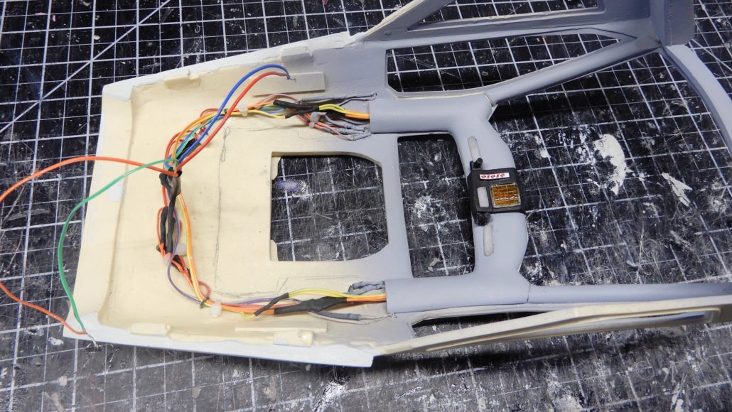
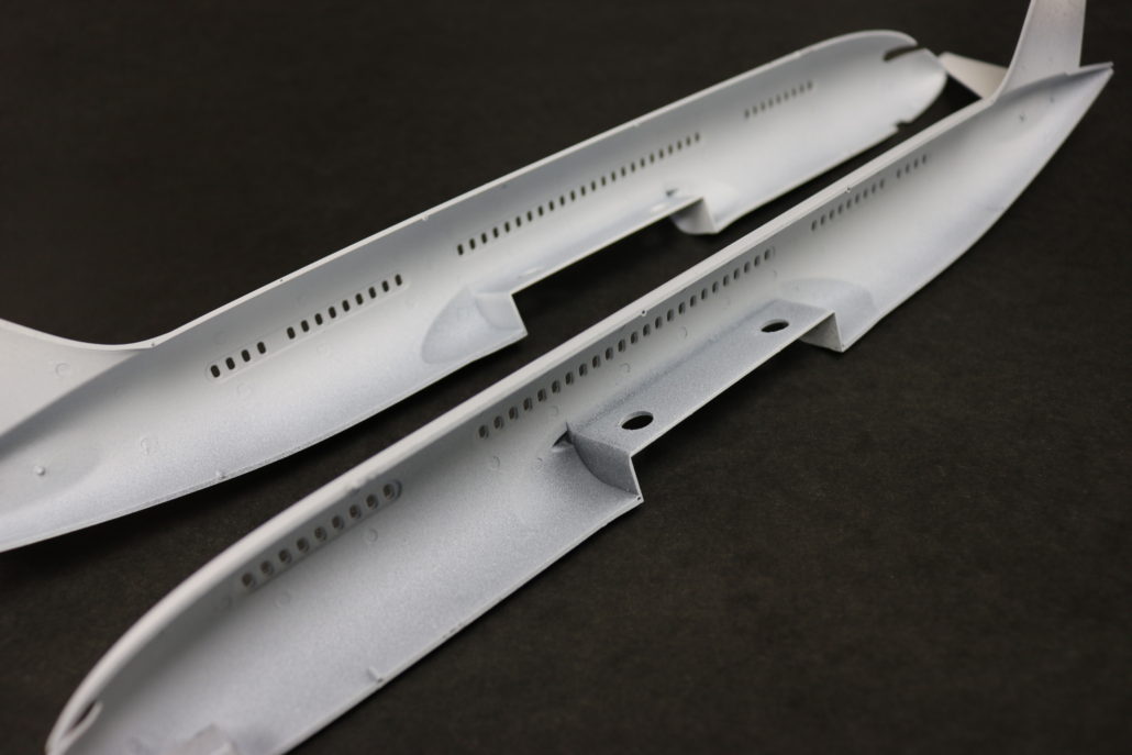
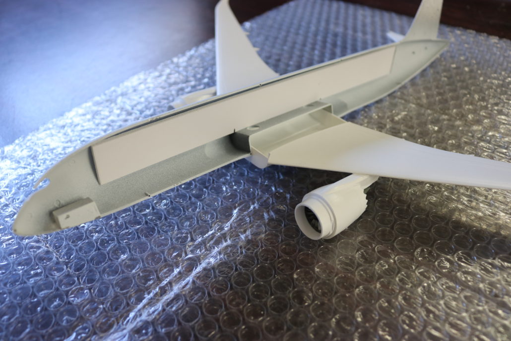
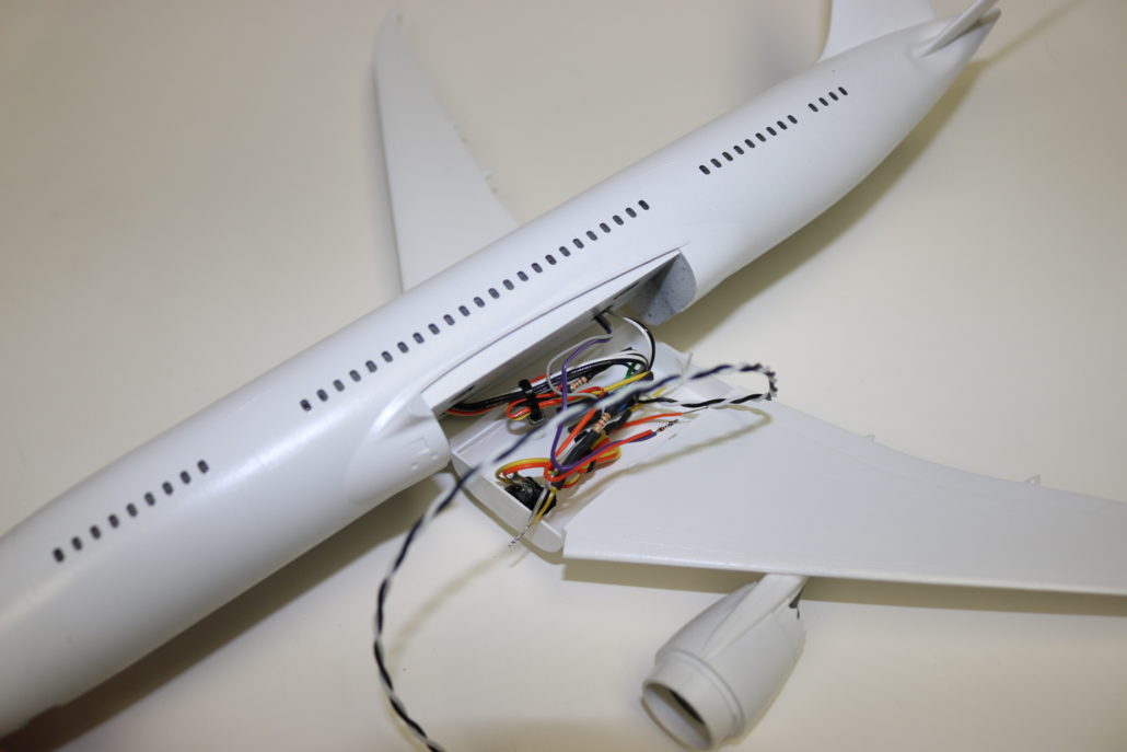
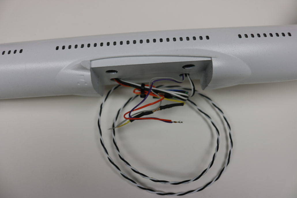
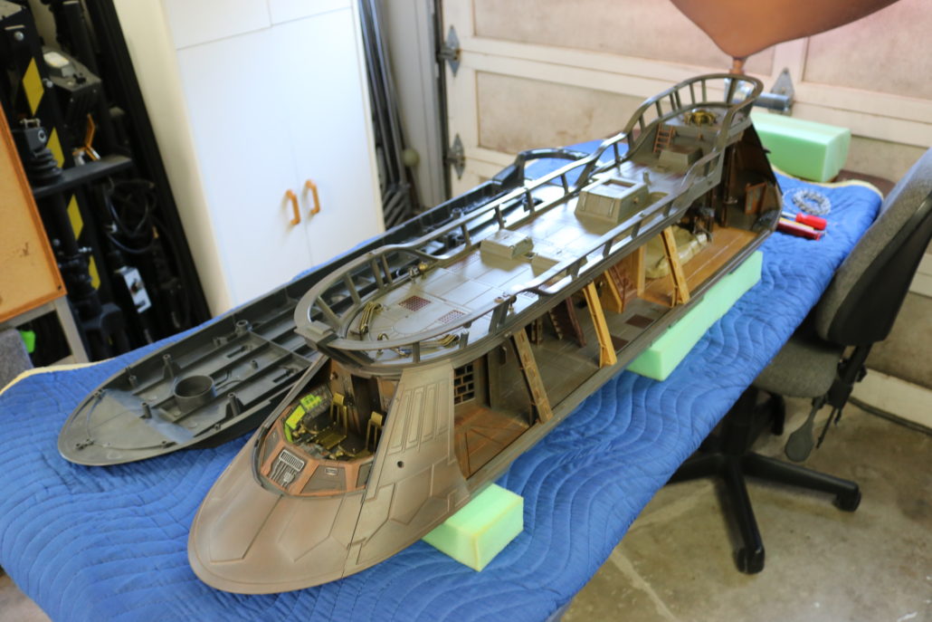
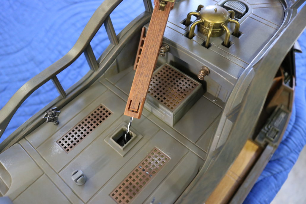
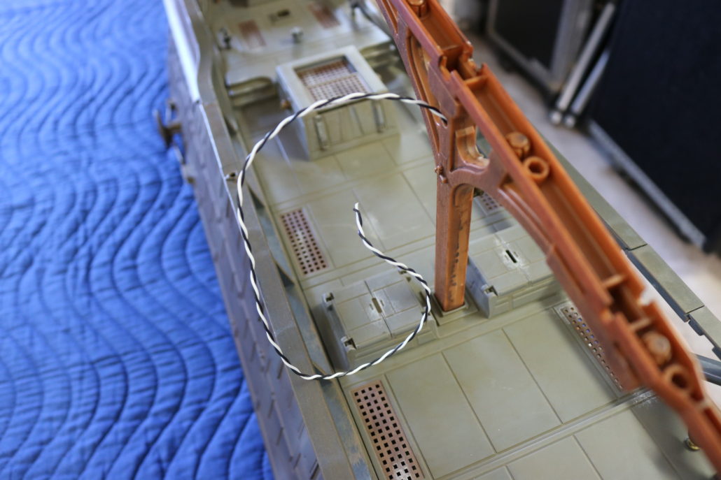
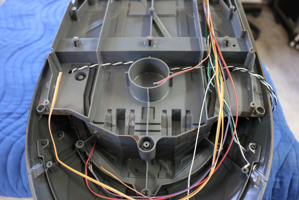
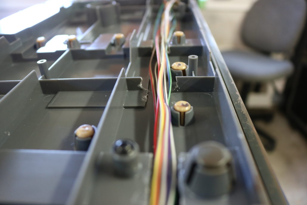
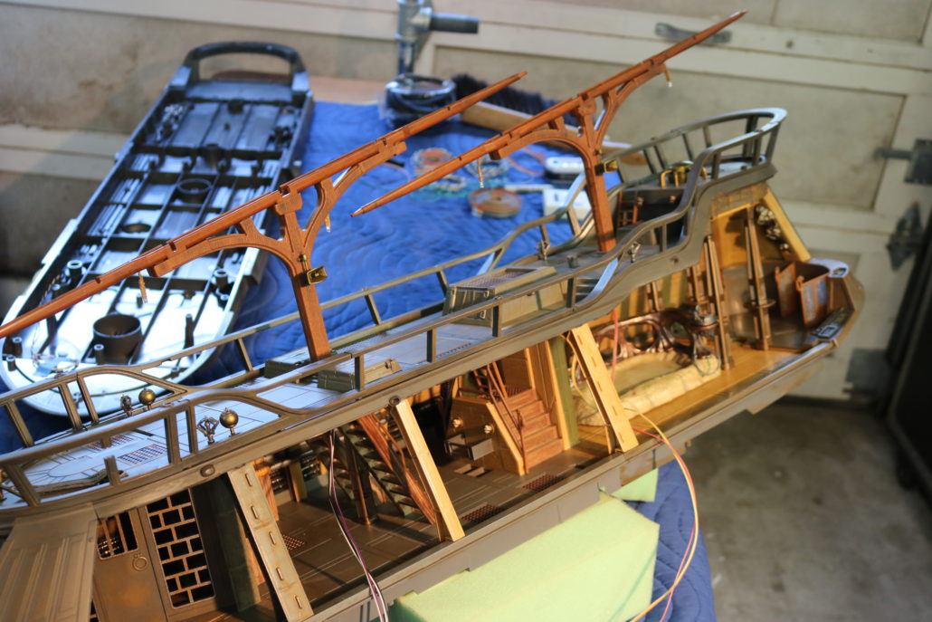
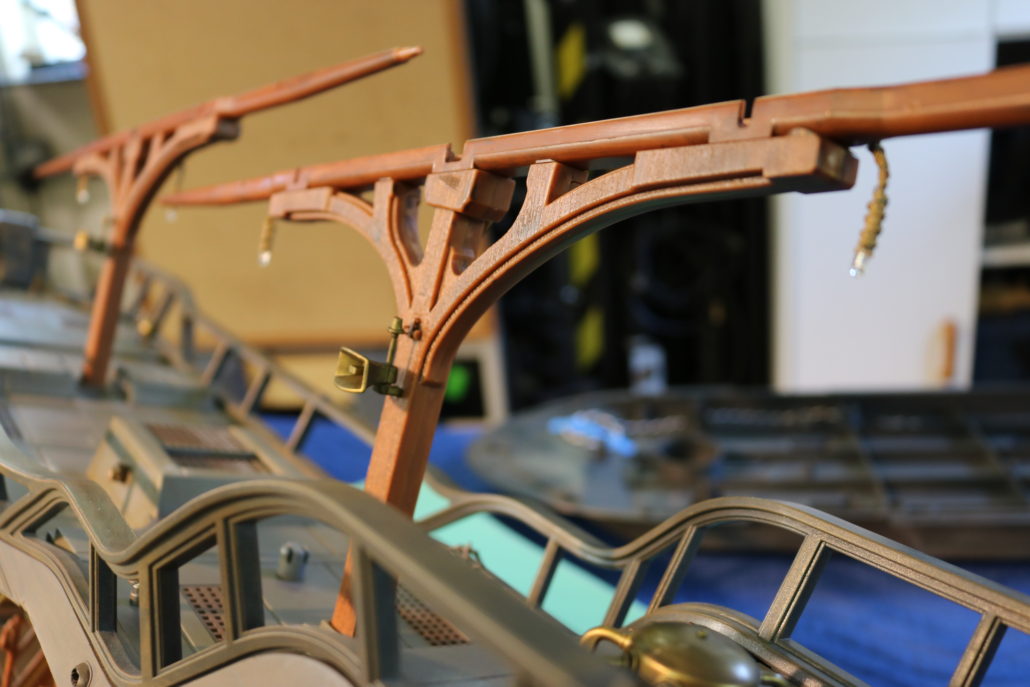
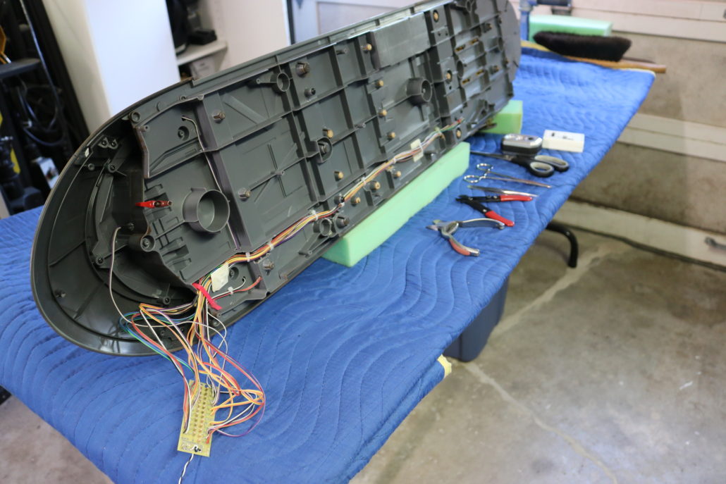
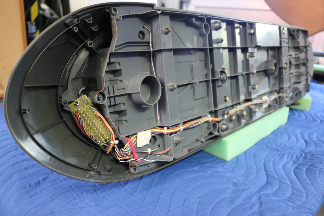
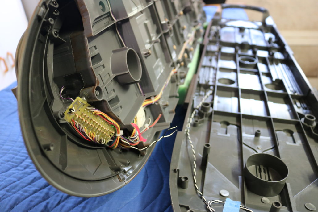
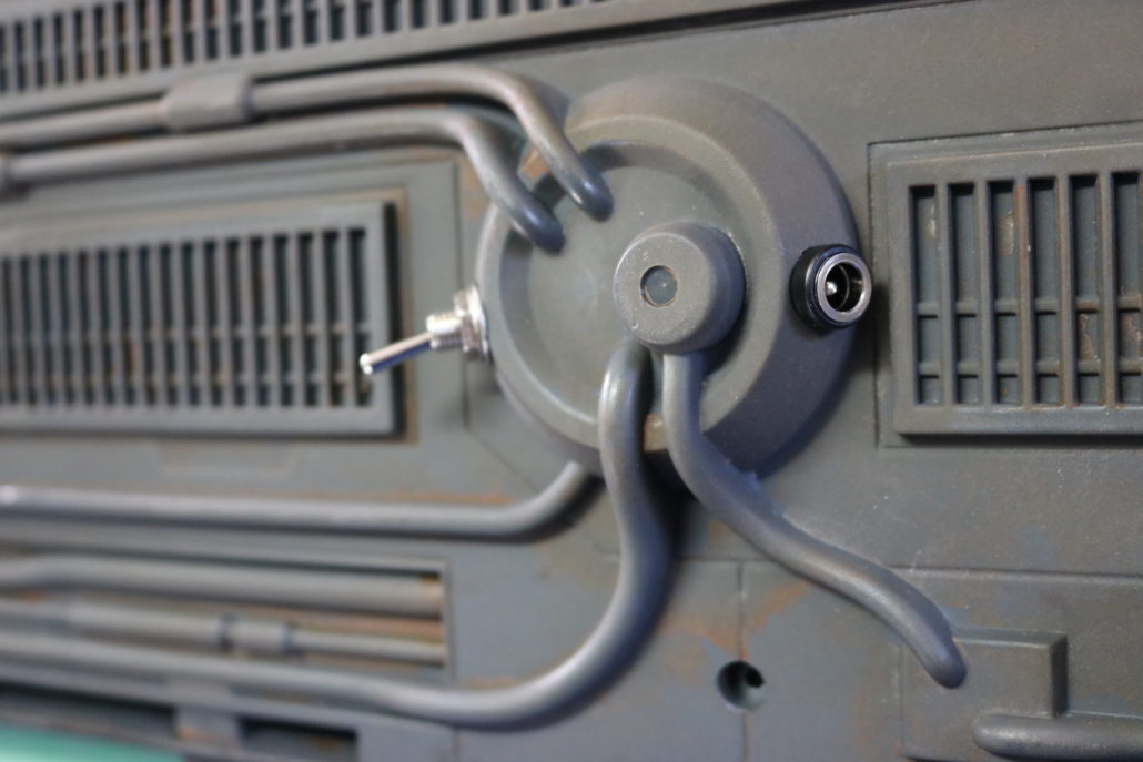
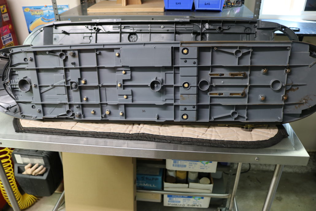
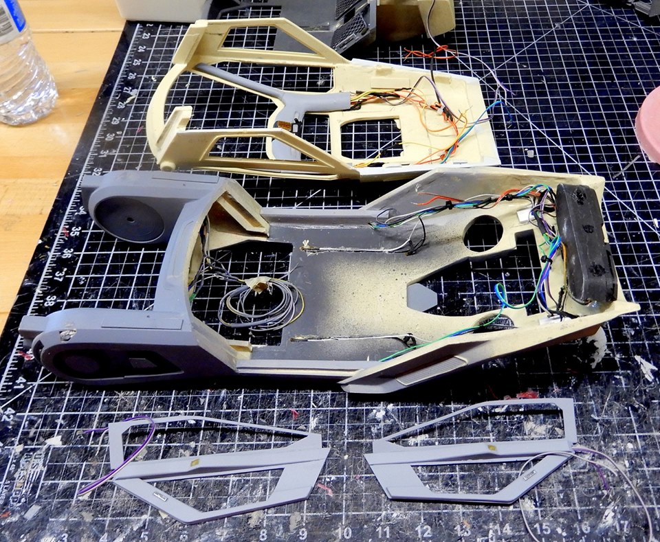
Main Body Layout
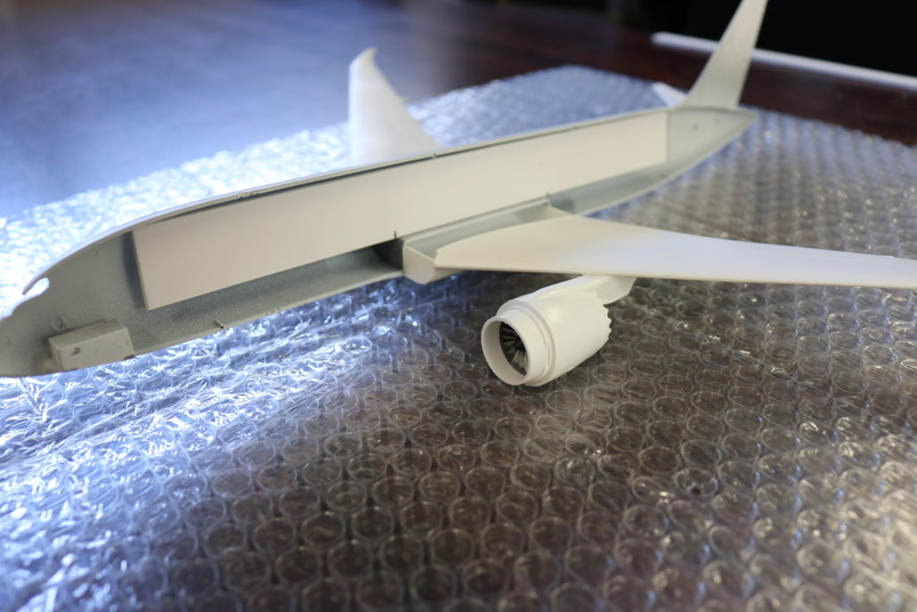
The main body comes in upper & lower body halves. When setting up for the electronics, you will need to build the lighting into the upper-main body as a separate lighting system. The final result would see few wire connections between the upper and lower sections. Prefabricate, paint & mount leds as you move through the model construction, testing lighting as you go.

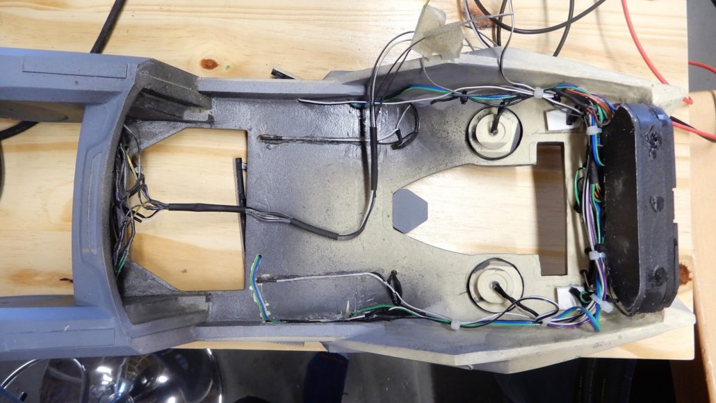
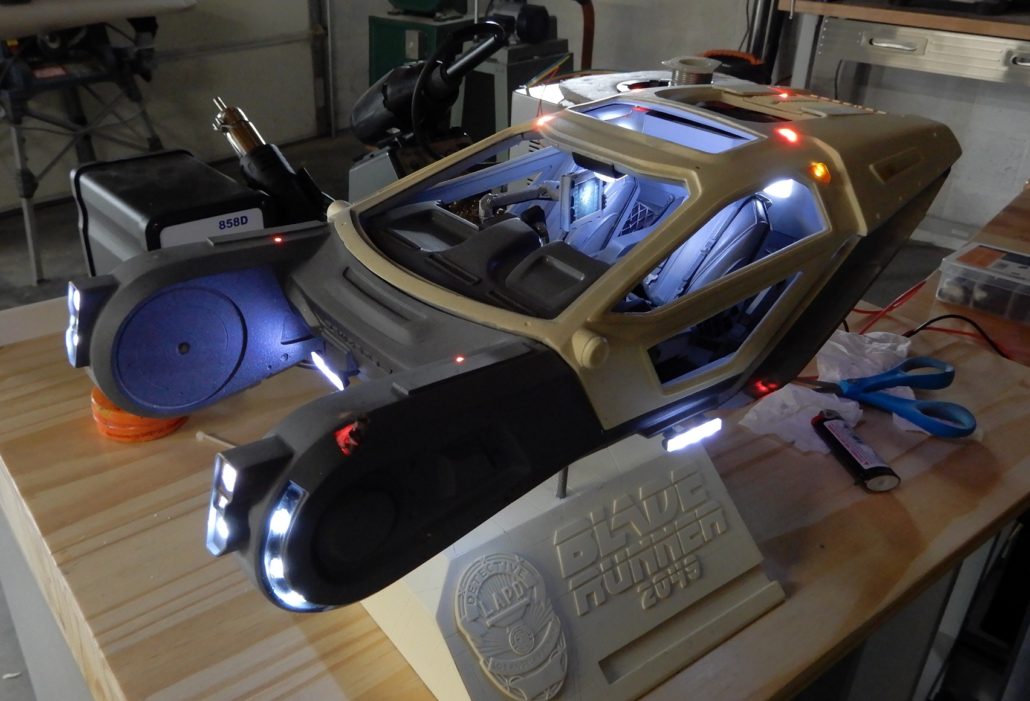
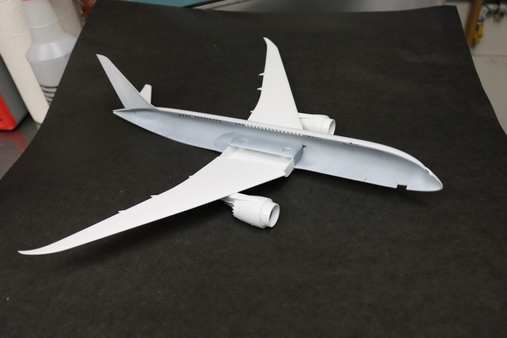
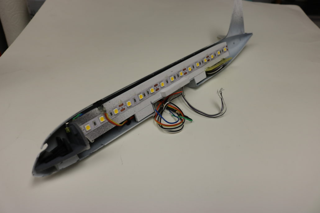
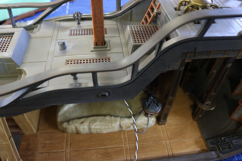
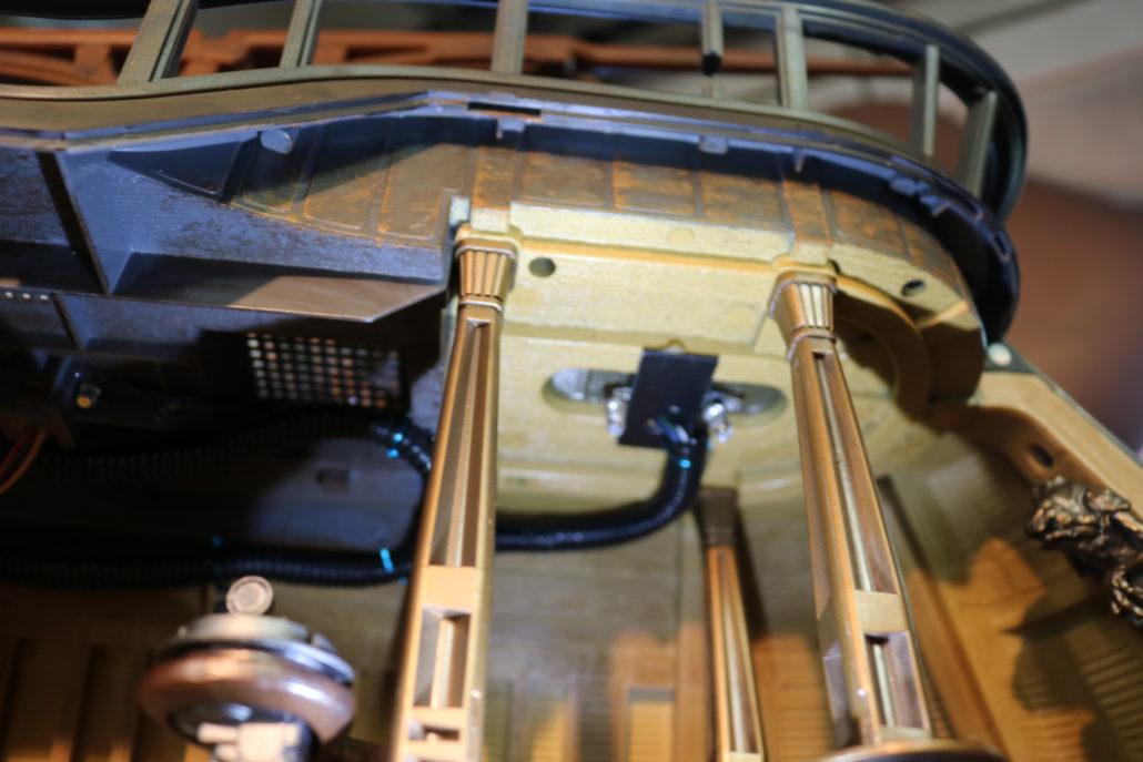
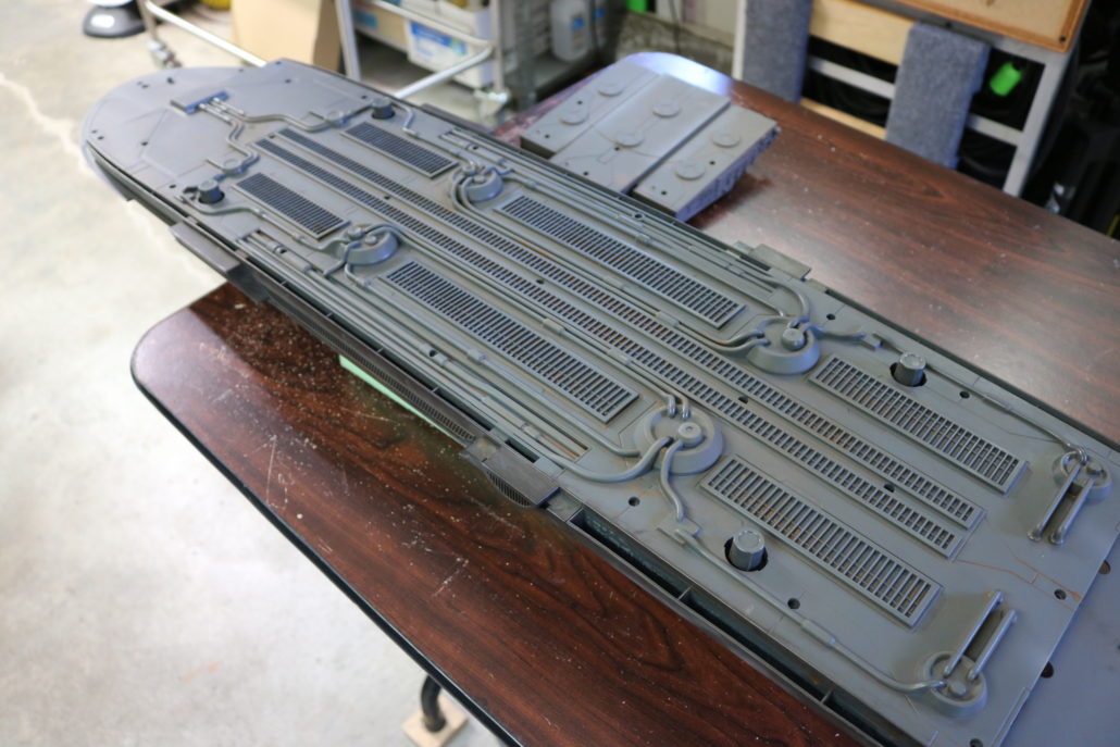
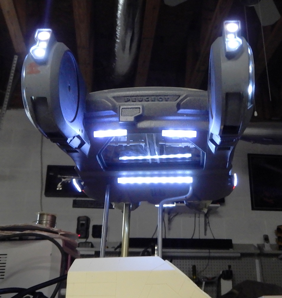
Exterior
The exterior has many light locations and will need to be installed along the build process.
Front main upper head lights X-2 W 5.0mm standard leds. Use 220-ohm resistor.
Front main lower head lights X-4 W 4.3mm small bookend style leds. Use 1.5 K ohm or 220-ohm resistor.

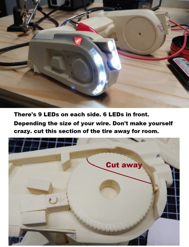
Front side wheel covers X-6 W 4.3mm small bookend style leds. Use 1.5 K ohm or 220-ohm resistor.
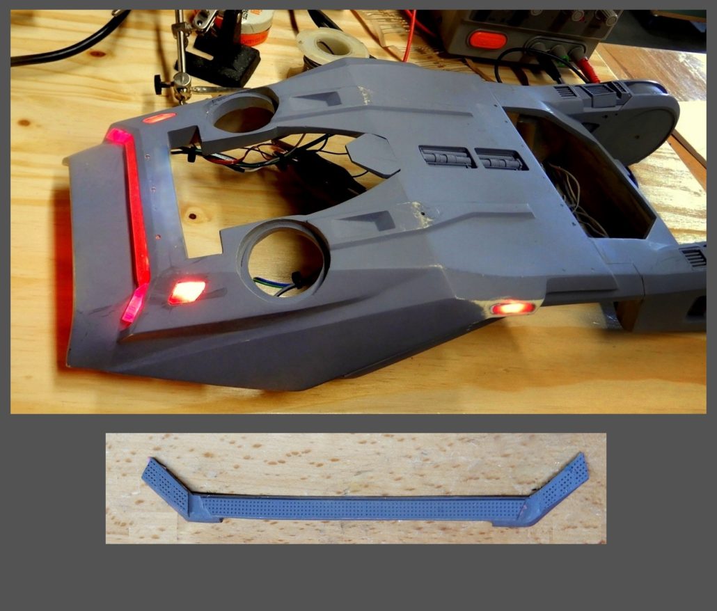
Front side upper turn signal X-2 R 3.0mm small standard style leds. Use 1.5 K ohm or 220-ohm resistor.
X-2 Lower Door accent 220 ohm resistor.

Top strobe 1 X-8 R 1.8mm super small led. Use 220-ohm resistors. Refer to reference material for locations.

Bottom strobe 2 X-8 W 1.8mm super small led. Use 220-ohm resistors. Refer to reference material for locations.
Rear main engine X-1 R 50/50 large strip leds. No resistor required. There will be some scratch building involved. A light box for the main rear engine area will need to be constructed.


Rear lower engine band X-1 R micro strip. No resistor required, see NOTES on soldering instructions.
Rear lower engine band sides X-2 R 3.0mm standard LED. Use 1.5K ohm resistor.
Bottom Lower flood light bars X-1 W micro strip. No resistor required, see NOTES on soldering instructions.
Rear license plate – X-1 W 4.8mm wide angle led. Use 1.5 K ohm resistor.
Bottom rear engine thrusters – X-2 W 5.0mm standard leds. Use 220-ohm resistor. Refer to EFFECTS LIGHTING.

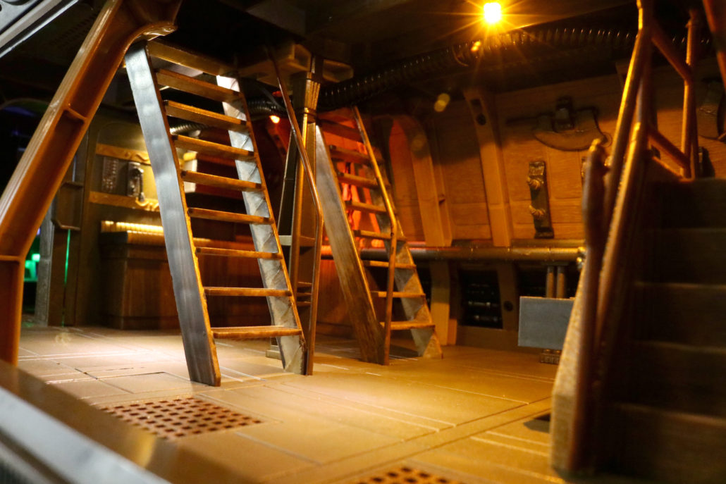
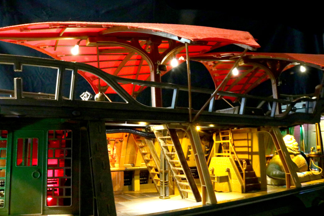
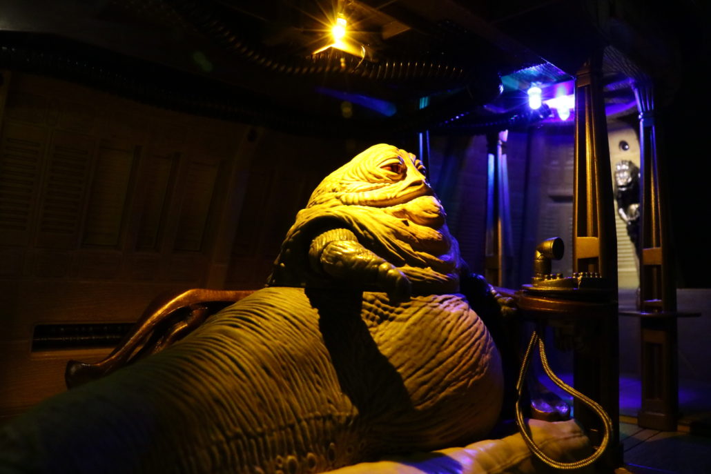
Photo Gallery